

SLIDE UML WEEK 2

Presentation
•
English
•
2nd Grade
•
Practice Problem
•
Hard

qzizz qzizz
FREE Resource
35 Slides • 0 Questions
1

Software Engineering
Modeling Software Systems using UML
2

LEARNING OBJECTIVES
1. Understand what is the UML and how the UML can be used to
model software systems.
2. Appreciate that the UML is a modeling language and not a
software development methodology.
3. Understand the basic modeling components of UML class
diagrams: class, association and generalization.
3

WHAT IS THE UML*?
General purpose visual modeling language for systems.
Incorporates current best practices in OO modeling techniques.
Software development methodology/process neutral.
Industry standard OO modeling language for modeling systems
(but can also be used for non-OO systems).
2.1
Basic Premise of the UML
A software system can be modeled as
a collection of collaborating objects.
* Unified Modeling Language
4


UML STRUCTURE
Building blocks
– things
– relationships
– diagrams
Common mechanisms
– specifications
– adornments
– common divisions
– extensibility mechanisms
Architecture
– use-case view
– logical view
– implementation view
– process view
– deployment view
UML
Common
mechanisms
Architecture
Building blocks
5
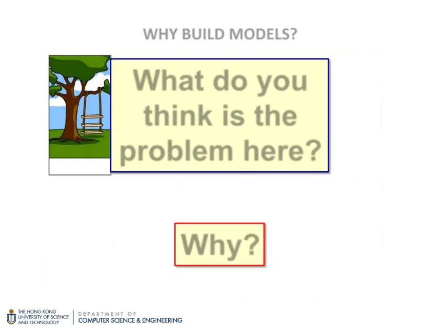
How the customer
explained it.
How the Project Leader
understood it.
How the Analyst
designed it.
How the Programmer
implemented it.
How the Business
Consultant described it.
How the project was
documented.
What operations installed.
How the customer was
billed.
How it was supported.
What the customer really
needed.
What do you
think is the
problem here?
WHY BUILD MODELS?
Why?
6
Models succinctly describe reality (i.e., they abstract reality).
They show essential details and filter out non-essential details.
For software development, this allows us to focus on the “big
picture”,
i.e., programming-in-the-large.
Such a focus allows us to better deal with the complexity of
software development,
i.e., with human limitations in understanding complex things.
The result is better understanding of requirements, cleaner
designs, and more maintainable systems.
WHY BUILD MODELS?
2.3.1
7
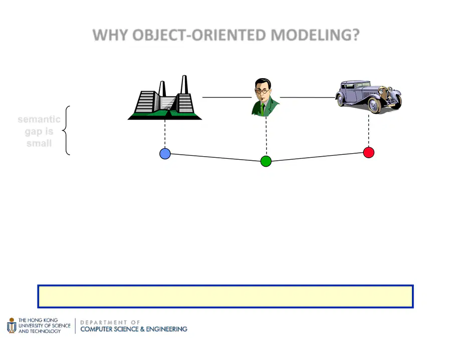
Organization
Person
Car
WorksFor
Owns
model
(objects)
semantic
gap is
small
WHY OBJECT
-
ORIENTED MODELING?
application
domain
Works for
Owns
Organizations
People
Cars
An application domain is modeled as a collection of objects.
☞ Allows direct representation of “things” in an application domain.
☞ Reduces the “semantic gap” between the
application domain and the model.
☞ Better represents how people think about reality.
8
Requirements level → We construct a requirements model.
– We do not consider any aspects of the implementation of objects.
☞ Focus: identifying objects (concepts) in the application domain.
Analysis & Design level → We construct a solution model.
– We consider interfaces of objects (but no internal aspects).
☞ Focus: how objects interact in the solution.
Implementation level → We implement the solution model.
– We consider all details of objects (external and internal).
☞ Focus: how to code objects.
OO MODELING & LEVELS OF ABSTRACTION
The same OO concepts can be used at all levels.
2.3.5
9
UML and Object-oriented Modeling
– Overview of the UML
– Object-oriented Modeling
Class
– Attribute
– Operation
Association
– Multiplicity
– Aggregation and Composition
Association Class
Generalization
– Inheritance
– Coverage
Constraints
2
MODELING SOFTWARE SYSTEMS USING UML:
OUTLINE
10
withdraw(amount)
payInterest()
deposit(amount)
balance()
account#: 16784565
amount: $2,000
withdraw(amount)
payInterest()
deposit(amount)
balance()
account#: 34829981
amount: $20,000
withdraw(amount)
payInterest()
deposit(amount)
balance()
account#: 87563412
amount: $5,000
withdraw(amount)
payInterest()
deposit(amount)
balance()
account#: 29851097
amount: $15,000
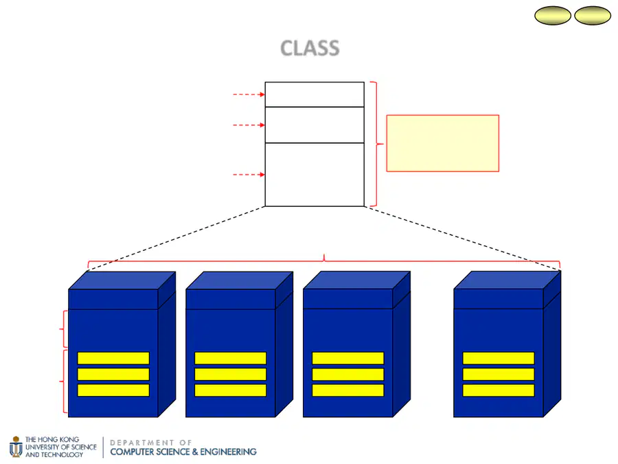
class name
attribute compartment
operation compartment
Account
account# : int
amount : money
balance( ) : money
deposit(amount)
withdraw(amount)
payInterest( )
class
A template used
to create objects.
balance
deposit(amount)
withdraw(amount)
balance
deposit(amount)
withdraw(amount)
balance
deposit(amount)
withdraw(amount)
balance
deposit(amount)
withdraw(amount)
Eva’s account
Sung’s account
…
bank account objects (instances)
Sam’s account
Fred’s account
CLASS
attributes
operations
2.4.2
2.3.3
11
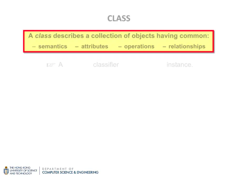
☞
A class is a
classifier; an object is an
instance
.
A class is a “factory” for creating objects.
A good class should capture one and only one abstraction.
☞ It should have one major theme.
A class should be named using the vocabulary of the application
domain (class names must be unique).
☞ So that it is meaningful and traceable from
the application domain to the model.
CLASS
A
class
describes a
collection of objects
having common:
–
semantics
–
attributes
–
operations
–
relationships
12
CLASS:
ATTRIBUTE
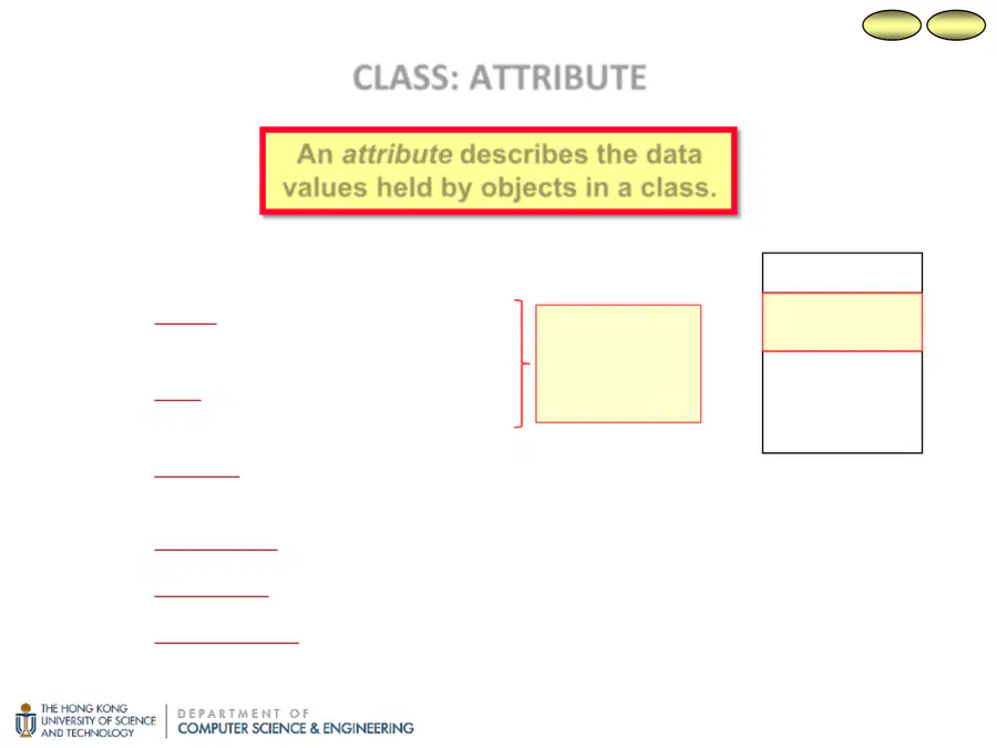
Attribute properties:
– name: unique within a class,
but not across classes.
– type: the domain of values –
string, integer, money, etc.
– visibility: who can access the attribute's values.
public (+), private (–), protected (#), package (~)
– initial value [optional]: the attribute's initial value.
– multiplicity [optional]: the number of simultaneous values.
– changeability: whether the value can be changed.
unspecified (default)
readOnly
An
attribute
describes the
data
values
held by objects in a class.
5.4.8
2.3.3
For modeling,
name and type
should always
be specified.
Account
balance( ) : money
deposit(amount)
withdraw(amount)
payInterest( )
account# : int
amount : money
13
CLASS:
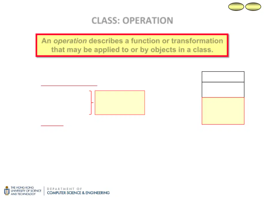
OPERATION
Operation properties:
– operation signature
operation name
parameter names
result type
– visibility
public (+), private (–), protected (#), package (~)
An operation instance (its implementation) is called a method.
☞ An operation can have several methods that implement it
(polymorphic operation).
An
operation
describes a
function
or
transformation
that may be
applied to or by objects
in a class.
2.4.2
2.3.3
For modeling, all
should always be
specified.
Account
account# : int
amount : money
balance( ) : money
deposit(amount)
withdraw(amount)
payInterest( )
14
WHY CLASSES FOR MODELING SYSTEMS?
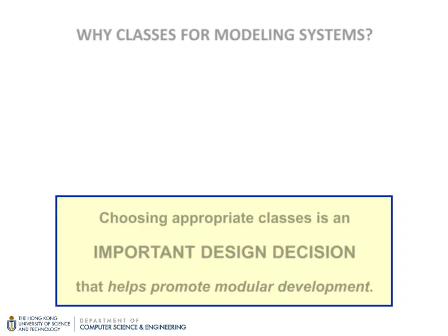
By abstracting a collection of objects and representing them as a
class, the complexity of developing a system is reduced since it
becomes easier to:
understand the system → We need to understand only the
classes, not the individual objects.
specify the system → Classes provide a place to define and store
common definitions only once.
Choosing appropriate classes is an
IMPORTANT DESIGN DECISION
that
helps promote modular development
.
15
UML and Object-oriented Modeling
– Overview of the UML
– Object-oriented Modeling
Class
– Attribute
– Operation
Association
– Multiplicity
– Aggregation and Composition
Association Class
Generalization
– Inheritance
– Coverage
Constraints
2
MODELING SOFTWARE SYSTEMS USING UML:
OUTLINE
16
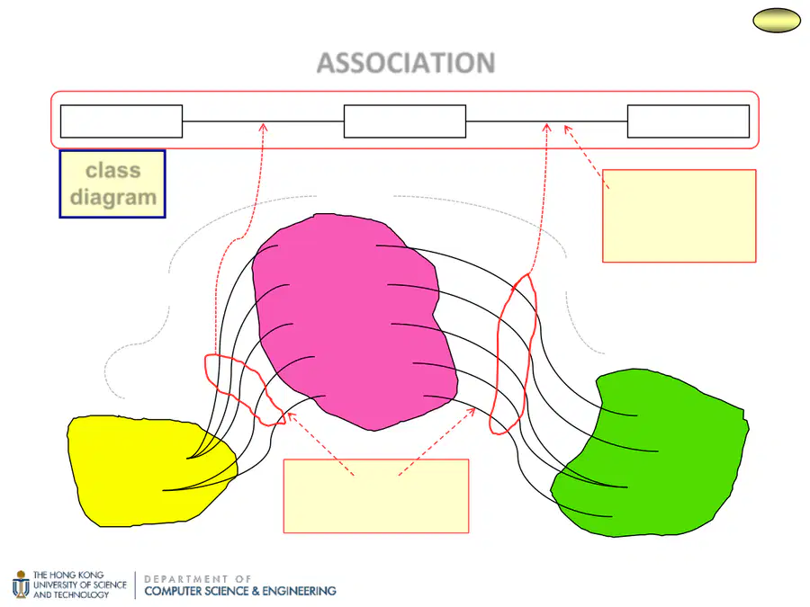
ASSOCIATION
2.4.2
Holds
IsWith
Account
16784565
34829981
29851097
88763459
87563412
Bank
HSBC
BEA
Customer
Fred
Eva
Sung
Sam
link
A relationship (instance)
between objects.
Bank
Account
Customer
Holds
IsWith
association
A description of
the links between
two objects.
class
diagram
17
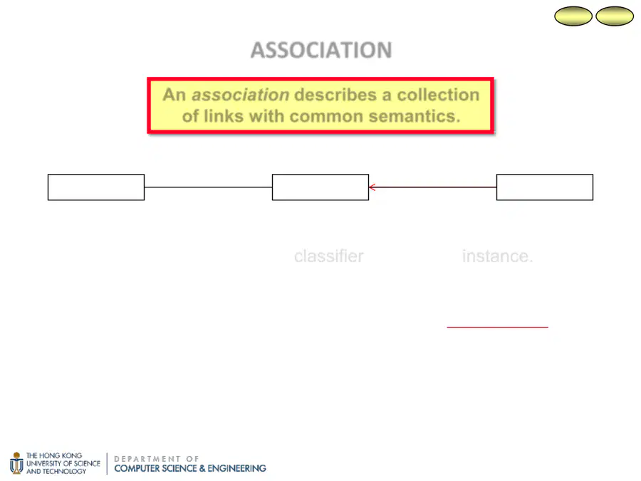
☞ An association is a
classifier; a link is an
instance
.
☞ Conceptually, associations are inherently bi-directional.
☞ Can show navigability of associations with an arrowhead.
(Implies that the source object has a reference to the target object.)
ASSOCIATION
An
association
describes a
collection
of links
with
common semantics
.
5.4.6
2.4.2
Bank
Account
Customer
Holds
IsWith
18
ASSOCIATIONS AND CLASSES
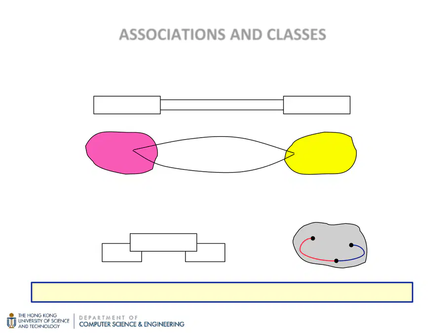
Two different classes can be related by several associations.
The same class can be related by several associations.
Person
University
Attended
WorksFor
James •
• HKUST
Attended
WorksFor
The collection of class and association names must be unique.
Person
Manages
MarriedTo
Jessie
Sam
John
MarriedTo
Manages
19
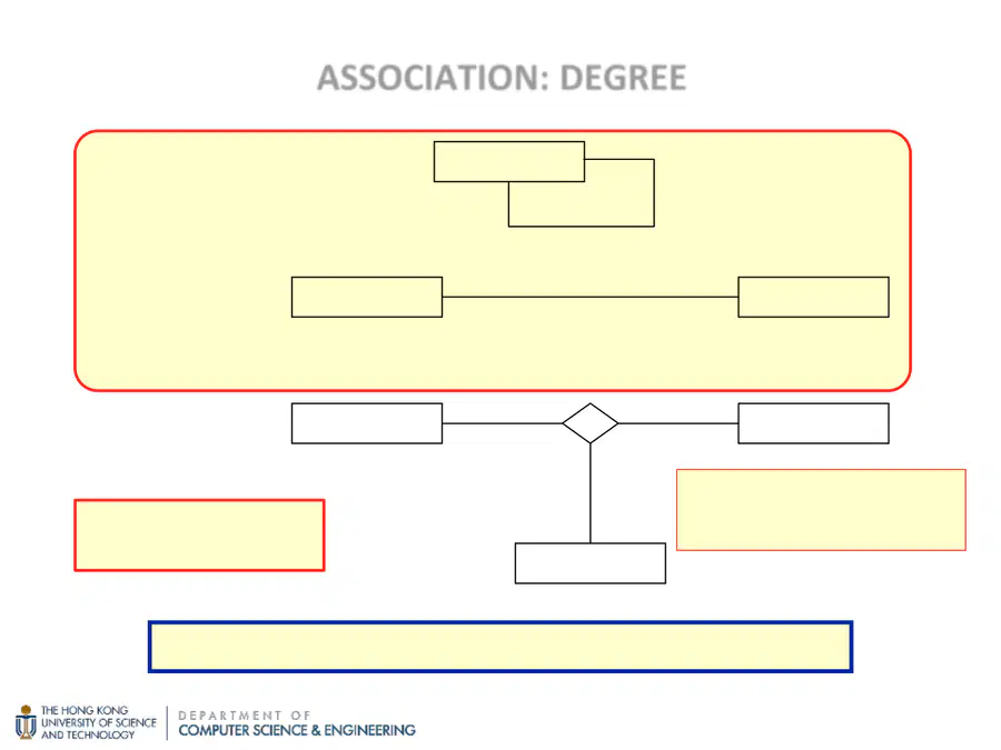
We will use only unary and binary associations in this course.
ASSOCIATION:
DEGREE
unary (reflexive)
relates one class to itself
Person
Manages
Higher degrees are
extremely rare!
In practice, the majority of associations are binary!
binary
relates two
classes
Customer
Account
Holds
ternary
relates three
classes
Project
Language
Person
A ternary relationship often can
be expressed as two binary
relationship, but not always.
20
ASSOCIATION:
MULTIPLICITY
0..*
1..1
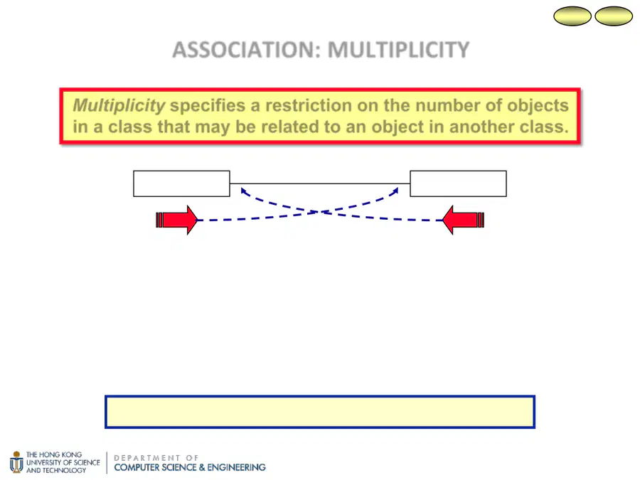
Multiplicity
specifies a
restriction
on the
number of objects
in a class
that may be
related to
an
object in another class
.
For a given bank, how many accounts can it have?
☞ A bank may have no accounts or it may have many accounts.
For a given account, how many banks can it be with?
☞ An account must be with exactly one bank.
Multiplicity is an application domain constraint!
Bank
Account
IsWith
5.4.6
2.4.2
21
N
ASSOCIATION:
MULTIPLICITY
(cont
'
d)
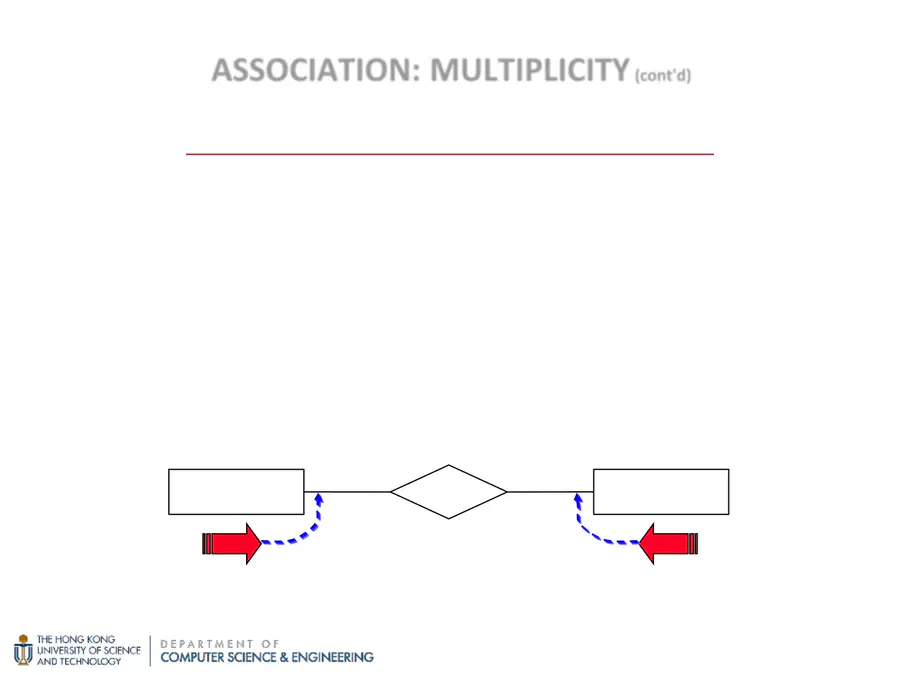
A NOTE FOR COMP 3311 STUDENTS
Both the ER model and the UML can represent the data
requirements of a system.
However, placement of the multiplicity in the ER model used in
COMP 3311 is different than that of the UML.
CAUTION: BE CAREFUL NOT TO MIX UP NOTATIONS!
1
Bank
Account
IsWith
22
ASSOCIATION:
MULTIPLICITY
(cont
'
d)
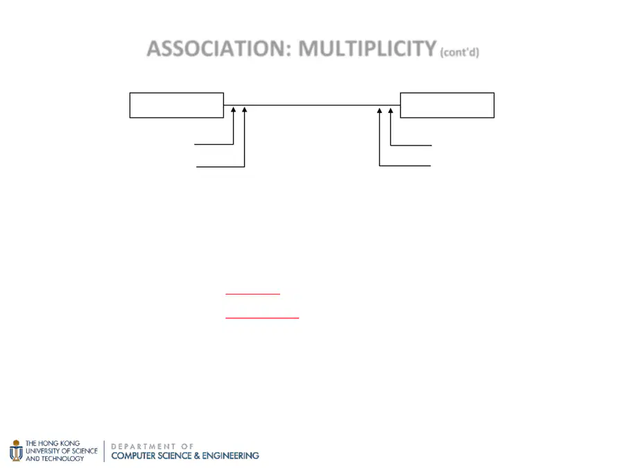
minimum cardinality (min-card)
min-card(C1,A): the minimum number of links in which each object of C1
can participate in association A
min-card(C1,A) = 0 → optional participation (may not be related)
min-card(C1,A) > 0 → mandatory participation (must be related)
maximum cardinality (max-card)
max-card(C1,A): the maximum number of links in which each object of
C1 can participate in association A
min-card(C2,A)
min-card(C1,A)
max-card(C2,A)
max-card(C1,A)
C1
C2
A
c..d
a..b
23
ASSOCIATION:
MULTIPLICITY
(cont
'
d)
special cardinalities:
max-card = * → an unlimited upper bound (∞)
min-card = 1 and max-card = 1 → can use 1 by itself
min-card = 0 and max-card = * → can use * by itself
0..*
1..11
*
Account
Bank
IsWith
24

These are the multiplicities that one would deduce from the above
statements, but they do not make sense (e.g., there cannot be 10 students
enrolled in a course at the time that the course is created).
THINK FOR A MOMENT!
Do these multiplicities make sense to you?
0..5
0..4510..45
?
1..5
?
MULTIPLICITY EXAMPLE
Student
Course
EnrollsIn
A student must enroll in at least one course and
can enroll in at most five courses
A course must have at least ten students enrolled
in it and cannot have more than forty-five students
enrolled in it.
25
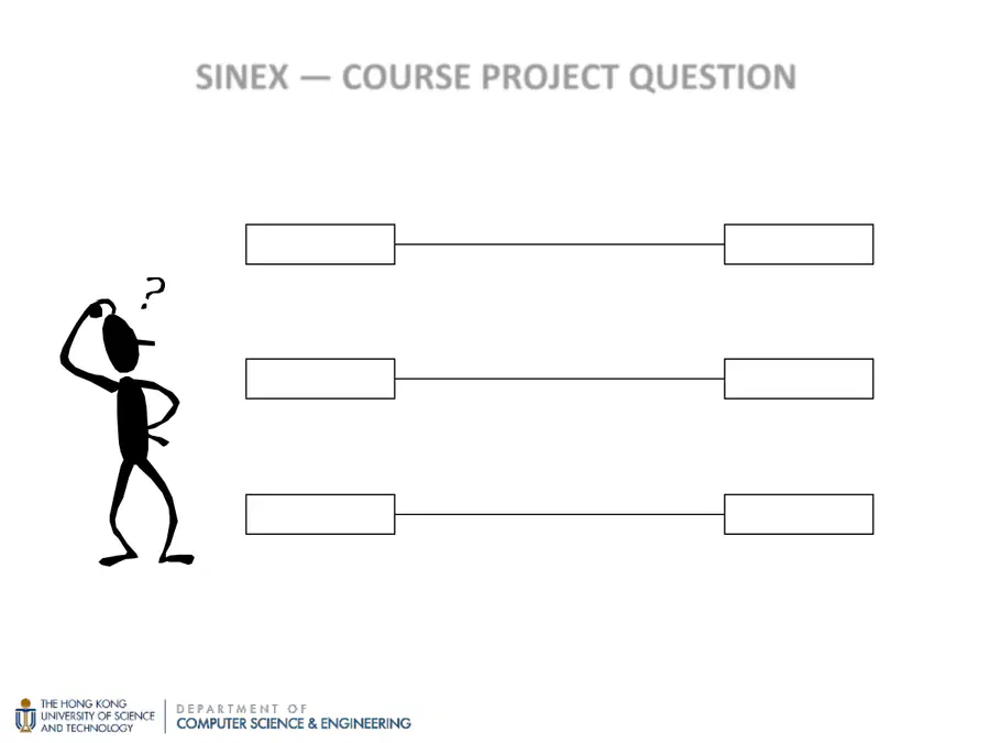
Shipment
City
SentTo
What is the most likely multiplicity of the following associations?
SINEX
—
COURSE PROJECT QUESTION
Customer
Shipment
Makes
Shipment
Package
Contains
1
*
1
1..*
*
1
26
ASSOCIATION:
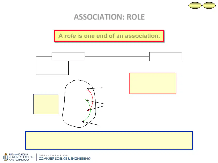
ROLE
A
role
is
one end
of an association.
employee
employer
For unary and
binary associations
there are two roles.
5.4.6
2.4.2
Person
Company
Works-for
boss
worker
Manages
boss
boss
worker
It is necessary to use role names when an association
relates objects from the same class.
Who
manages
who?
John
Sarah
Frank
Bill
27
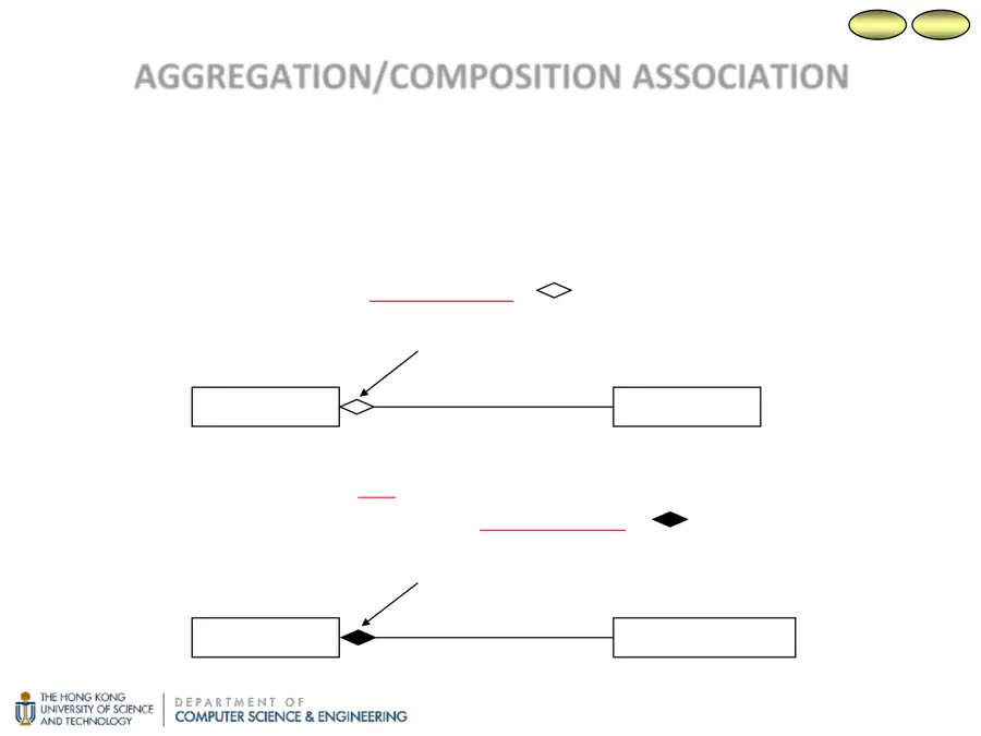
A special type of association in which there is a “part-of”
relationship between one class and another class.
☞ A component may exist independent of the aggregate object of
which it is a part → aggregation. [
adornment]
AGGREGATION/COMPOSITION ASSOCIATION
☞ A component may not exist independent of the aggregate
object of which it is a part → composition. [
adornment]
Disk
Computer
Has
min-card = 0; max-card = 1 (may be * in some cases)
Room
Building
Has
min-card = 1; max-card = 1 (may be * in some cases)
5.4.7
2.4.2
28
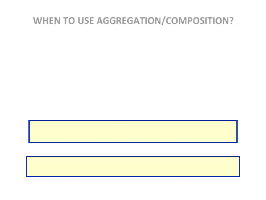

WHEN TO USE AGGREGATION/COMPOSITION?
Would you use the phrase “part of” to describe the association or name
it “Has”?
☞ BUT BE CAREFUL! Not all “Has” associations are aggregations.
Is there an intrinsic asymmetry to the association where one object
class is subordinate to the other(s)?
Are operations on the whole automatically applied to the part(s)? →
composition
It is not wrong to use association rather than aggregation!
(In a real project, when in doubt, use association!)
The decision to use aggregation is a matter of judgment.
It is a design decision.
29
UML and Object-oriented Modeling
– Overview of the UML
– Object-oriented Modeling
Class
– Attribute
– Operation
Association
– Multiplicity
– Aggregation and Composition
Association Class
Generalization
– Inheritance
– Coverage
Constraints
2
MODELING SOFTWARE SYSTEMS USING UML:
OUTLINE
30


MODELING SOFTWARE SYSTEMS
USING UML
EXERCISE
31

for OO because in UML we're trying to
capture a set of important objects
within the model. If we are talking about
a set of objects, then it's going to be very
suitable for OO [inaudible]. But it also can be used
for non-OO systems. The basic idea of UML is that we try to represent
the system using a collection of
important objects that exist within
the software system. This is the structure of UML. Within an UML, we have different
building blocks, we have different building
blocks that we can use for drawing the model. For example, the important things that we have
within the model, different relationships, and different diagrams that we
can use to model the system. Also, we have some
common mechanisms. For example, we can provide additional texture
descriptions within the model. Also, we can include additional adornments,
for example, you try to draw some
additional things or additional adornments
within the diagram. Also, some common divisions, some extra definition
that you can provide to force you to think about
a world in a certain way. Also, extensibility mechanisms for you to extend the model. We can
build a model from
different perspectives. For example, from
the use-case view, logical view,
implementation view, process view, or
deployment view. In this lecture, I'm
going to talk about the building blocks that we can use for drawing class diagram. Within UML,
there are different diagrams
that we can draw. In this lecture, we will
talk about class diagram. In some of the
upcoming lectures, we will talk about
use-case diagram and also State Machine Diagram. Within class diagram, we
are trying to capture all the data requirements
32

within a software system. So we try to capture all the data requirements
in a form of a collection of objects
and their relationships. If we are talking about
the use-case diagram, we try to capture all
the functionalities provided by the system. Finally, if we are talking about the State Machine
Diagram, we are talking about
trying to capture all the possible states that we can have
within an update. These are the three
diagrams that we're going to cover within this course, the class diagram,
use-case diagram, and also State Machine Diagram. Why do we build models? Let's study this
example, which is pretty interesting. This may be how the customer
explained about a project. Then this may be how the
project leader understand it. This may be how the
analyst decided it. This may be how the
programmer implemented it. Then how the business
consultant described it, and how the project
was documented. No documentation at all. What operations installed. How the customer was
billed. How he was supported, and what the customer really needs or maybe it's going to
be just something simple. What's the problem here? The problem here is
actually communication. Just because different
stakeholders, they may have different
ideas in their mind. That's why at the very
beginning of the project, we need to build a model so
that when we communicate, we can communicate
using the model. To make sure that all
the stakeholders, they're going to have
the same idea in their mind by just take
a look at the model. Why do we build models? Let me just talk about
another example. For example, let's say
when we build an airplane. Why do we want to
build the model of an airplane before we
actually build a plane? Because you know that the plane itself is going to
33

be very complicated. So that's why we're
going to skip some of the complicated details within the plane and then we're going
to build a simpler model. This is what we
call abstraction. We try to skip details and we build a model which
is going to be simpler. But still somehow
from the model you can visualize all the
details within the plane. Then we can use the
plane, that model, the model of the plane, to communicate with different stakeholders within
the project. That's why we need a model. Because we need a model
to communicate with different people that we
have within the project. The models that we're
going to build is going to describe reality. For example, the model of the airplane is going to
somehow describe the actual airplane. But here we'll talk
about abstraction, we try to skip details within
the model of the plane. We try to show the essential details that
we need for communication, and we try to filter out
the non-essential details maybe just because the airplane itself is going to be
can be very complicated. So we're going to skip some of the complicated things within
the airplane in the model. For software development,
this allows us to focus on the big
picture, that means, all the important
objects that we have within the software system, and this is what we mean by
programming-in-the-large. By focusing on the big picture, it allows us to better deal with the
complexity of
software development because the software itself, source code
implementation services can be very complicated. That's why instead of
talking about a source code, we build a model to capture all important objects that we have
within the software system. This is going to
help us deal with the complexity within
a software project. The result of a
model is that we get better understand all the requirements
within the product, putting their design, and also more maintainable
34

software systems because we understand the software system
better through a model. Why object-oriented modeling? Just because it's natural to represent
things
using objects. For example in the
application domain, we have organizations,
we have people, and then we have cars. Then people, they work for
different organizations and also they own
different cars. Then I just have natural to
map all these things within indeed application domain as different objects that
we have in the model. Within the model, we
have organization, we have person, and we have car, and then we connect them
together using relationships. For example, person they
work for organization, and person they work for, and we connect them together
using associations. For example person
they works for organization and person
they own different cars. It's natural to represent things using the application
domain using objects, and it's going to reduce the gap between the application
domain and also the model. This is natural to map
things as different objects, and also better represent how
people think about reality. That's why in this lecture, we're going to talk
about how we can use a class diagram to capture a collection of important objects that we have
within the application domain. If we are talking
about OO modeling, there are different
models that we can build. We can build a model to capture all the requirements within
the software system. In this model, we simply try to identify all the
important objects, all the important things, or all the important objects, or all the important
concept that we want to keep track within
the software system. Then we also can come up
with a solution model. So somehow we go
through analysis and design and then we
build a solution model. That model is going
to be the model that we're going to use
35

for implementation. That means, when we implement, this are the objects that we're
going to implement within the software system and
also implementation level. Eventually we're
going to implement the solution model and turn the solution model into
a set of source code or a set of code objects. The same OO concepts can
be used at all levels. In this course, we are going
to focus on two models. One is the requirement model, to capture all the
data requirements, all the important
objects that we need within a software system. Also how we design, how we actually design the
solution model that we're going to use for implementation. In this lecture, we focus
on requirement model. Again, just keep in mind that if we are talking about
the requirement model, it has nothing to do
with implementation. So just given the
application domain. We try to capture all
important objects within the application
domain, that's it. It has nothing to do
with implementation. If we are talking
about implementation, we are talking about
the solution model. Solution model is the one that we use for implementation, but not
requirement model. Requirement model is
going to be simple. We know that this
are things that exist within the
activation domain. We try to capture
all this things within a requirement model. The requirement model
is going to help us understand all requirements, all the things that we need
within the software system.
Software Engineering
Modeling Software Systems using UML
Show answer
Auto Play
Slide 1 / 35
SLIDE
Similar Resources on Wayground

27 questions
Domain 11 Lesson 1: E Pluribus Unum
Presentation
•
2nd Grade
28 questions
REVIEW (the world and transportation)
Presentation
•
KG
33 questions
Petrified Pirates Vocab Lesson
Presentation
•
KG - 2nd Grade
23 questions
/au/ /aw/ Spelling words
Presentation
•
2nd Grade
30 questions
EOG Prep 8
Presentation
•
8th - 12th Grade
26 questions
Past Tense Regular Verb
Presentation
•
2nd Grade
25 questions
Subject and Predicate
Presentation
•
3rd Grade
29 questions
Wonderful Ecuador
Presentation
•
2nd Grade
Popular Resources on Wayground
6 questions
PRIDE Always and Everywhere
Presentation
•
12th Grade
20 questions
Lab Safety Quiz

Quiz
•
6th Grade
26 questions
KOR Review Kahoot Questions
Quiz
•
8th Grade
21 questions
Continents and Oceans
Quiz
•
6th Grade
12 questions
Unit Zero lesson 2 cafeteria
Presentation
•
9th - 12th Grade
20 questions
Parts of Speech
Quiz
•
5th Grade
10 questions
Riddles Riddles fun Riddles
Quiz
•
6th - 12th Grade
16 questions
Subject & Predicate
Quiz
•
5th Grade
Discover more resources for English
24 questions
CKLA Domain 1 review (Fairy tales/ tall tales)
Quiz
•
2nd Grade
13 questions
Nouns!
Quiz
•
2nd Grade
20 questions
nouns verbs adjectives test
Quiz
•
2nd Grade
5 questions
Grandma and the Great Gourd Vocabulary
Quiz
•
2nd - 3rd Grade
13 questions
R Blends
Quiz
•
1st - 2nd Grade
20 questions
Sentence or Fragment?
Quiz
•
2nd - 5th Grade
20 questions
Statements and Questions
Quiz
•
2nd Grade
11 questions
Picture Day Perfection
Quiz
•
2nd Grade