

LV03 Basic electrics and circuits

Presentation
•
Specialty
•
University
•
Medium

Kate Sollers-Dominey
Used 3+ times
FREE Resource
24 Slides • 32 Questions
1
Open Ended
What skills are you developing?
What can you do now that you could not do before you started with us?
2
Basic Automotive Electrics
3
What is electricity?
Electricity is the flow of electric charge, typically in the form of electrons, through a conductor. It is a fundamental force of nature and is crucial for our modern society. It powers our homes, businesses, and numerous electronic devices we depend on every day. Understanding the basics of electricity is essential in understanding how circuits work and how to create electrical systems.

4
Every substance is made up of molecules.
All molecules are made up of atoms.
All atoms have an electrical charge.
What is Electricity?


5
Electricity starts at an atomic level. When electrons move from one atom to the next, current is produced.
Electrons are negatively charged.
Protons are positively charged.
The further away from the nucleus the electrons are, the weaker their bond.
How current is produced.


6
Volts is electrical pressure
Amps is electrical flow
Resistance is a restriction to the current flow
Watts is electrical power
Electrical units
7
Voltage
Voltage, also known as electric potential difference, is a measure of the force that pushes electric charges through a conduction path in an electrical circuit.
It is typically measured in volts (V) and represents the difference in electric potential between two points in a circuit.
In simple terms, voltage can be thought of as the pressure or strength of the electric current flowing through a circuit.
8
Amps
Amps, short for amperes, is the unit of measurement used to quantify the rate at which electric current flows in a circuit.
The higher the amperage in a circuit, the greater the rate of electric charge flow.
Too much current flow in a circuit will produce excessive heat which can lead to a fire.
Sometimes the letter I is used for amps. This stands for Intensity. It is derived from a French translation
9
Resistance
Resistance is expressed as R.
In an electrical circuit, resistance reduces the flow of current and converts some of the electrical energy into heat.
Resistors are used in circuits to control the flow of current, limit voltage, divide voltage, and perform various other functions.
The higher the resistance in a circuit, the lower the current that will flow through it for a given voltage.
10
Watts, denoted by the symbol "W," is the unit of measurement used to quantify power in an electrical circuit.
It represents the rate at which electrical energy is consumed or produced. One watt is defined as one joule of energy per second.
Wattage is commonly used to express the power of electrical devices or systems, including light bulbs, kitchen appliances, and electronic equipment.
The wattage of a device is usually specified on its label or documentation and helps users understand how much energy the device consumes or produces.
Watts
11

Voltage, amps and resistance are all linked and affect each other.
We can use simple calculations to work this out.
Ohms Law
12

Likewise, Watts, Amps and Volts are all linked and can be worked out using this calculation.
Watts triangle
13
Voltage, Amps and Ohms

14
Name as many conductors and insulators as you can
The difference between a conductor and an insulator is that a conductor allows the easy movement of electrons, and an insulator restricts the movement of electrons.

15
Insulators
Replace this text with your body text.
Duplicate this text as many times as you would like.
Conductors
16
Glass, rubber, plastic, ceramic, wood, air, fibreglass, porcelain, quartz, and mica are all examples of electrical insulators.
Insulators
Copper, aluminium, silver, gold, iron, nickel, brass, bronze, carbon (in the form of graphite), platinum, zinc, tungsten, lead, tin, and mercury are all commonly used as electrical conductors.
Conductors
Conductors and insulators
17
What is a circuit?
A circuit is a complete path that allows electricity to flow. It consists of a power source (such as a battery or generator), conductive wires (usually made of copper), and components (such as resistors, switches, or light bulbs) connected in a closed loop. When the circuit is complete, electricity can flow continuously, creating a flow of electrons. Understanding the different types of circuits, such as series and parallel circuits, is vital for constructing and troubleshooting electrical systems.
18
Drag and Drop
19

Series circuits are those where the components are connected in series, forming a single path for electricity to flow. In series circuits, the total resistance increases as more components are added.
Series Circuits

20
Open Ended
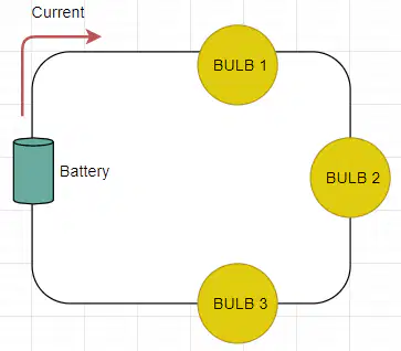
What do you think happens if bulb 2 blows?
21
The fundamental rules for series circuits:
The amount of current is the same through any component in a series circuit.
Components in a series circuit share the same current:
Itotal = I1 = I2 = . . . In
Current:
22
Voltage
Total voltage in a series circuit is equal to the sum of the individual voltage drops:
Vtotal = V1 + V2 + . . . Vn
23
Labelling
Drag the correct voltages over the MM testing points. What voltage would you expect to see here?
0v
8v
4v
12v
24
Resistance
When components (such as lamps) are added in series, the total resistance increases. The combined resistance is equal to the sum of individual resistances.
[ R = R1 + R2 + R3 + ....... ]
25
Current is consistent.
Resistance accumulates.
Voltage adds up.
Remember
In a series circuit

26
Parallel Circuits
What is a Parallel Circuit?
A parallel circuit is a type of electrical circuit that contains multiple branches with components connected side by side.

27
Open Ended
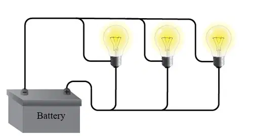
What would happen if the first bulb blew?
28
There are three important rules to remember in a parallel circuit: the voltage across each branch is the same, the current divides, and the resistance decreases.
Rules of a parallel circuit

29
Work out your individual resistances first then divide 1 by the whole total.
This will give you the whole circuit resistance.
We use the formula
Calculating resistance in a parallel circuit
30
Open Ended

What is this type of circuit?
31
Open Ended

What would happen if bulb 1 blew?
32
Open Ended

What would happen if bulb 3 blew?
33
Fill in the Blanks
34
Fill in the Blanks
35
Fill in the Blanks
Type answer...
36
Fill in the Blanks
Type answer...
37
Fill in the Blanks
Type answer...
38
Fill in the Blanks
Type answer...
39
Multiple Choice
Which of the following statements is true?
Series circuits have a higher total resistance than parallel circuits.
Parallel circuits have a higher total resistance than series circuits.
Series circuits have a higher total current than parallel circuits.
Parallel circuits have a higher total current than series circuits.
40
Open Ended
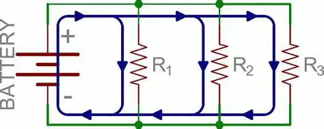
Using the calculation Rt=(R11+R21+R31⋅⋅⋅⋅)1 What would be the total resistance if all the resistors were 4 Ω?
41
Open Ended
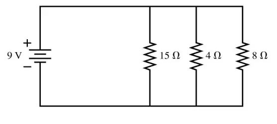
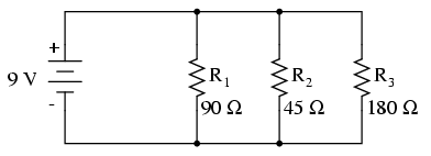
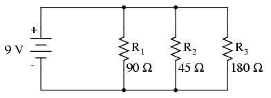
Calculate the total resistance of the circuit.
42
Multiple Choice

43
Multiple Choice
44
Multiple Choice
45
Multiple Choice
46
Multiple Choice

47
Multiple Choice
48
Multiple Choice
49
Multiple Choice
50
Multiple Choice
51
Multiple Choice
52
Multiple Choice

53
Multiple Choice
54
Multiple Choice
55
Multiple Choice
56
Multiple Choice
What skills are you developing?
What can you do now that you could not do before you started with us?
Show answer
Auto Play
Slide 1 / 56
OPEN ENDED
Similar Resources on Wayground

52 questions
Classification
Presentation
•
University
51 questions
Lesson 1. Understanding Technology Learners
Presentation
•
University
51 questions
User Behaviour Basics
Presentation
•
University
52 questions
SPANISH EXPLORATION LESSON AND ASSIGNMENT
Presentation
•
KG - University
51 questions
L21 Inflation and the Federal Reserve
Presentation
•
University
51 questions
Nouns
Presentation
•
University
53 questions
Bahasa Inggris 2 Meeting 2 and 3
Presentation
•
University
Popular Resources on Wayground
11 questions
Hallway & Bathroom Expectations

Quiz
•
6th - 8th Grade
10 questions
HCS SCI 03 Summer School Assessment 2
Quiz
•
3rd Grade
11 questions
Home Scope
Quiz
•
7th - 8th Grade
12 questions
2026 TAP Technology in the Classroom
Presentation
•
Professional Development
15 questions
HCS SCI 05 Summer School Assessment 2 Review
Quiz
•
5th Grade
15 questions
HCS SCI 04 Summer School Review 2
Quiz
•
4th Grade
59 questions
Geometry Unit 3 Review
Quiz
•
9th - 12th Grade
14 questions
FAST ELA READING SMAPLE TEST MATERIALS

Passage
•
3rd Grade