
Search Header Logo
Onshape and Technical Drawing

Onshape and Technical Drawing

Assessment

Presentation

Mathematics, Other

Practice Problem

Medium

Created by

D'Shayln O'Neil

Used 4+ times

FREE Resource

12 Slides • 35 Questions

1

Multiple Choice

Question image

In using Onshape to make a PART, first, you Create -> Document, then choose Sketch, then what do you have to do?

1

Choose which plane (front, top or right) to draw

2

Extrude the 2d sketch to make a 3d part

3

Choose the size of your drawing

4

Set the Workspace units

2

Designing the Future

Exploring Computer Aided Design

3

Introduction to CAD

  • Computer Aided Design (CAD) is a technology that enables designers to create, modify, and analyze designs digitally.
  • CAD software allows for precise measurements, 3D modeling, and simulation, improving design accuracy and efficiency.
  • With CAD, designers can visualize and test their ideas before production, reducing costs and time.
  • Popular CAD software includes AutoCAD, SolidWorks, and CATIA.

4

5

Multiple Choice

What is the purpose of CAD software?

1

To enable designers to create, modify, and analyze designs digitally

2

To improve design accuracy and efficiency through precise measurements, 3D modeling, and simulation

3

To visualize and test ideas before production, reducing costs and time

4

To explore the future of computer-aided design

6

Improving Design Efficiency

  • CAD software enables designers to create, modify, and analyze designs digitally.
  • It improves design accuracy and efficiency through precise measurements, 3D modeling, and simulation.
  • By visualizing and testing ideas before production, it reduces costs and time.

7

Understanding CAD Software

  • CAD stands for Computer Aided Design
  • CAD software is used to create, modify, analyze, and optimize designs
  • It allows for precise measurements, 3D modeling, and simulation
  • Common CAD software includes AutoCAD, SolidWorks, and CATIA
  • Used in various industries like architecture, engineering, and manufacturing

8

Multiple Choice

What is the purpose of CAD software?

1

To create, modify, analyze, and optimize designs

2

To measure and model in 3D

3

To simulate designs

4

To explore computer aided design

9

Design Optimization

CAD software is used to create, modify, analyze, and optimize designs. It enables designers to efficiently explore different design options and improve the performance of their products. By simulating and testing designs virtually, CAD software helps in reducing costs, minimizing errors, and enhancing overall design quality. It revolutionizes the design process by providing powerful tools for visualization, measurement, and modeling in 3D.

10

Computer Aided Design:

  • Creating 2D Designs
  • Utilize CAD software to design precise 2D models
  • Draw lines, shapes, and dimensions with ease
  • Modify and edit designs effortlessly
  • Enhance productivity and accuracy in design process

11

Multiple Choice

What can CAD software be used for?

1

Creating 2D designs

2

Analyzing data

3

Writing code

4

Managing finances

12

Creating 2D designs

CAD software is widely used in industries like architecture and engineering to create precise and detailed 2D designs. It allows designers to easily manipulate and visualize their ideas, improving efficiency and accuracy. With CAD software, complex designs can be created with ease, revolutionizing the design process.

13

Computer Aided Design:

  • Designing the Future
  • Exploring 3D Models
  • Developing with Precision
  • Enhancing Creativity
  • Efficient and Time-saving

14

Multiple Choice

What is the main focus of Designing the Future: Exploring Computer Aided Design?

1

Developing with Precision

2

Enhancing Creativity

3

Efficient and Time-saving

4

Exploring 3D Models

15

Exploring 3D Models

Did you know? Computer Aided Design (CAD) allows designers to create and manipulate 3D models of objects. It revolutionized the design process, making it more efficient and time-saving. CAD software is widely used in industries like architecture, engineering, and product design. With CAD, designers can visualize and test their ideas before production, enhancing creativity and precision.

16

Computer Aided Design:

  • Simulating and Analyzing Designs
  • Explore the future of design with Computer Aided Design (CAD)
  • Simulate and analyze designs to optimize functionality and efficiency
  • Utilize advanced tools and algorithms to create innovative and precise designs
  • Enhance collaboration and communication among designers and engineers

17

Multiple Choice

What is the purpose of Computer Aided Design (CAD) in design?

1

To simulate and analyze designs for functionality and efficiency optimization

2

To enhance collaboration and communication among designers and engineers

3

To utilize advanced tools and algorithms for innovative and precise designs

4

To explore the future of design

18

CAD: Simulating and Analyzing Designs

  • Computer Aided Design (CAD) is used to simulate and analyze designs for functionality and efficiency optimization.
  • It enables designers to test and refine their ideas before physical production.
  • CAD tools utilize advanced algorithms to create innovative and precise designs.
  • Collaboration and communication among designers and engineers are enhanced through CAD.

19

Multiple Choice

Question image

Which individual sketch tool was used in the sketch below?

1

Arc

2

Offset

3

Fillet

4

Trim

20

Multiple Choice

Complete circles shall always be dimensioned using...

1

meters

2

diameter

3

lines

4

degrees

21

Multiple Choice

Which icons is the Line Tool, used to draw straight lines?

1
2
3
4

22

Multiple Select

[Multi-select] Select ALL answers that are correct.

Which of the following can be used to draw arcs (curved lines with specific radius)?

1
2
3
4

23

Multiple Select

[Multi-select] Select ALL answers that are correct.

Which of the following can be used to draw rectangular shapes?

1
2
3
4

24

Multiple Select

Question image

[Multi-select] Select ALL answers that are correct.

What can the Dimension Tool be used for?

1

Define angles between lines

2

Define distance between points/lines

3

Define length of lines

4

Define diameter of circles

5

Define radius of arcs

25

Multiple Choice

Which icon is the Sketch Fillet Tool, used to add fillets (rounded corners) on a sketch corner.

1
2
3
4

26

Multiple Choice

Which icon is the Mirror Tool, used to draw a copy of selected entities about a line

1
2
3
4

27

Multiple Choice

Which icon is Tangent Constraint, that constrains a curve and a line/other curve to be tangent (touch the curve but not cross it)

1
2
3
4

28

Multiple Choice

Which icon is the Parallel Constrain, that makes two or more lines parallel?

1
2
3
4

29

Multiple Choice

Which icon is the Trim Tool, used to trim/remove a selected line or curve?

1
2
3
4

30

Multiple Choice

Why do designers draw objects in 3D?
1
Because they find it easy
2
Because they are told to do so
3
Because it shows the user exactly what they are thinking
4
Because that's the way its always been done

31

Multiple Select

Question image

This is a ______________ drawing.

1

multiview

(orthographic)

2

photographic

3

pictorial

4

technical

32

Multiple Select

Question image

The six possible 2d projections of a 3d object are called this

1

orthographic views

2

photographic

3

pictorial

4

technical

33

Multiple Choice

Question image

Which orthographic view shows the width and depth of an object?

1

front

2

left

3

right

4

top

34

Multiple Choice

Question image

Which views most commonly get drawn for multiview (orthographic) drawings?

1

front, rear, right side

2

front, top, left side

3

front, top, right side

4

front, top, right, left, rear, bottom

35

Multiple Choice

Question image

What dimension is associated with an object’s top-to-bottom dimension?

1

Height

2

Width

3

Depth

4

Length

36

Multiple Choice

These lines are light dotted /dashed lines

1

Object

2

Center

3

Extension

4

Hidden

37

Multiple Choice

Question image
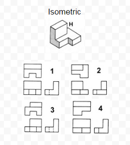
Which orthographic projection represents the correct views for the isometric sketch?
1
1
2
2
3
3
4
4

38

Multiple Choice

Question image

What is the front view?

1
2
3
4

39

Multiple Choice

Question image

What is the top view?

1
2
3
4

40

Multiple Choice

Question image

Which cube cannot be made based on the unfolded cube?

1
2
3
4

41

Multiple Choice

Question image

Which cube cannot be made based on the unfolded cube?

1
2
3
4

42

Multiple Choice

Question image
What type of drawing is this?
1
Planometric
2
Isometric
3
One-point perspective
4
Two-point perspective

43

Multiple Choice

Question image
Which view shows the block from the TOP
1
2
2
3
3
4
4
5

44

Multiple Select

The 3 orthographic views that make up the home view are ____(choose all that apply)

1

Top view

2

Front view

3

Rear view

4

Right side view

5

Bottom view

45

Multiple Choice

Question image

What will be the top view of the given isometric object?

1
2
3

46

Multiple Choice

Question image

Which is the correct front view of the figure provided?

1
2
3
4

47

Multiple Choice

Question image

A line that is short and long dashes that indicate a circular feature on a part is _____?

1
Object Line
2
Hidden Line
3
Construction Line
4
Center Line
Question image

In using Onshape to make a PART, first, you Create -> Document, then choose Sketch, then what do you have to do?

1

Choose which plane (front, top or right) to draw

2

Extrude the 2d sketch to make a 3d part

3

Choose the size of your drawing

4

Set the Workspace units

Show answer

Auto Play

Slide 1 / 47

MULTIPLE CHOICE