
 Worksheets
Maritime Drawing Mid Term Reviewer 2022
Total questions: 200
Worksheet time: 7hrs 40mins
Regardless of the language they speak, people all over the world use _______ drawings to communicate their ideas using a formal standard.
freehand
sketch
technical
artistic
Which is NOT intended of technical drawings?
Visualization
Communication
Documentation
Accreditation
Which is NOT communicated by technical drawings for a product or system?
Size
Price
Shape
Feature information
It is a dark, heavy lines that show the outline and shape of an object.
Visible line
Hidden line
Section line
Center line
It is light, narrow, short, dashed lines that shows the outline of a feature that can not be seen in a particular view.
Visible line
Hidden line
Section line
Center line
It is a thin line usually drawn at a 45 degree angle that indicates the material that has been cut.
Visible line
Hidden line
Section line
Center line
It is a thin line consisting of long and short dashes that shows the center of holes.
Visible line
Hidden line
Section line
Center line
It is a dark, heavy lines that show the length, width, and height of the features of an object.
Dimension line
Cutting-plane lines
Short-break line
Long-break line
It is thick broken line that is terminated with short 90 degree arrowheads that shows where a part is mentally cut in half to better see the interior detail.
Dimension line
Cutting-plane lines
Short-break line
Long-break line
It is a thick wavy line that used to break the edge or surface of a part for clarity of a hidden surface.
Dimension line
Cutting-plane lines
Short-break line
Long-break line
It is used to show that the middle section of an object has been removed so it can be drawn on a smaller piece of paper.
Dimension line
Cutting-plane lines
Short-break line
Long-break line
It is thin lines made up of long dashes alternating with pairs of short dashes to show the alternate position of moving parts.
Phantom line
Cutting-plane lines
Short-break line
Long-break line

Top
Front
Rear
Bottom

Right-side
Left-side
Top
Rear

Right-side
Left-side
Top
Rear

Which is the third-angle projection?
(A)
(B)
Both (A) and (B)
None of the above
Which is the first-angle projection?
(A)
(B)
Both (A) and (B)
None of the above

Which is the correct section view of the image?
(A)
(B)
(C)
(D)

Which is the correct way of lettering?
(A)
(B)
Both (A) and (B)
None of the above
To space the distance from one letter to the next within a word or sentence is by _________ .
vertical guidelines
eye while lettering
incline guidelines
computation
Lettering in engineering drawings is typically _____ case.
inclined
lower
upper
italic
In drawing only one style of lettering or font which is either inclined or ______ should be used.
vertical
horizontal
top
bottom
Putting equal distances from letter to letter causes them to appear ______ spaced.
equally
uniformly
unequally
limited
Draw horizontal strokes from ________ with a wrist movement and without turning the paper.
left to right
right to left
top to bottom
bottom to top
Draw curved and inclined strokes with ______ motion.
upward
downward
upward and downward
no
Hard grade pencil with designation of 9H, 8H, 7H, 6H, 5H, 4H are used in _________ .
guidelines and construction lines
lettering and object line
artwork
charcoal drawing
Medium grade pencil with designation of 3H, 2H, H, F, HB, B are used in _________ .
guidelines and construction lines
lettering and dark lines
artwork
charcoal drawing
Which is NOT appropriate way of lettering?
Letters and numbers are done in freehand.
Mechanical pencils should be used instead of wooden pencils since no reshaping is needed.
Light guidelines should be erased after lettering and drawing dark lines.
Light guidelines should be used for uniform height of letters.
Arrange the drawing sheet from largest to smallest size.
A4, A3, A2, A1, A0
A0, A1, A2, A3, A4
A5, A4, A3, A2, A1
A1, A2, A3, A4, A5
What is the smallest drawing sheet available at the school with paper size of 210mm x 297mm ?
A0
A1
A3
A4
Which is NOT proper among the important skills for drawing?
Accuracy - no drawing is useful unless it shows the information correctly.
Speed - time is money in industry so work smarter by learning to use techniques to speed up your drawing even if it looks messy.
Legibility - a drawing is a means of communicating with others so it must be clear and understandable.
Neatness - if a drawing is to be accurate and legible, it must be clean.
Which is NOT true in freehand drawing?
A helpful way to organize your thoughts and record ideas.
It provide a quick, low-cost way to explore various solutions to design problems.
The term freehand sketch does mean a sloppy drawing.
It requires only pencil, paper, and eraser.
Which is NOT correct in drawing lines?
Make dimension, extension, and centerlines thin, sharp, and dark.
Make hidden lines medium and light.
Make visible and cutting-plane lines thick and dark.
Make construction lines thin and light.
Which is NOT correct in drawing lines?
Keeping your eye on the mark toward which you are moving.
Apply more pressure to make a dark line.
Apply more pressure to make thin and light line.
Do not start lettering without guidelines.
Which two drawings are useful for showing objects that have cylindrical shapes built on axes or centerlines?
Oblique
Isometric
Orthographic
Perspective
Which is NOT true in oblique projection?
Oblique drawing is an easy method for creating quick pictorials.
Circles in the front oblique plane are true size and shape.
Circular shapes are easy to sketch in the front oblique plane but they would appear elliptical in the top or sides.
The angle at the other side of the plane is only at 45 degree angle.
Which is true in oblique projection?
Oblique projections look natural to us.
Use in drawing large objects.
The angle at the other side of the plane could be 30, 45 and 60 degree angle.
Circular shapes appear elliptical both in oblique and isometric views.
Which is NOT true about assembly drawing?
Assembly drawings are used to show how parts fit together.
An exploded isometric assembly drawing shows the individual parts moved apart from one another along the isometric axis line directions.
The parts list on it include a number identifying each item and its quantity.
Seeing how the parts fit together in assembly will not help the manufacturer understand the entire device and not identify potential problems.

Phantom line
Extension line
Object line
Section line

Dimension line
Center line
Object line
Section line

Dimension line
Cutting-plane line
Break line
Section line

Dimension line
Extension line
Object line
Section line

Hidden line
Cutting-plane line
Break line
Phantom line

Dimension line
Cutting-plane line
Leader line
Section line
By projecting multiple views from different directions in a systematic way, you can completely describe the shape of ___ objects.
3D
2D
Plain
4D
Which is NOT true about projection of views?
United States and Canada use the third-angle projection.
Europe and Asia use the first-angle projection.
In the third-angle the top view placed above the front view and the right side view at the right of the front view.
In the first-angle the top view placed above the front view and the right side view at the right of the front view
Which is NOT true about orthographic projection?
Describe the shapes of objects exactly and completely.
A two-dimensional view.
A three-dimensional view.
Top, front and side view.
The word _______ means “at right angles.”
orthographic
isometric
oblique
perspective
Which is NOT a pictorial view?
Orthographic view
Isometric view
Oblique view
Perspective view
A miter is a line with ______ degree angle which is used in transferring dimension from top to right side view in third-angle projection.
30
45
60
90
Which is NOT true regarding lines in an object?
Thick, dark lines represent features of the object that are directly visible.
Thin, dark lines represent features of the object that are directly visible.
Dashed lines represent features that would be hidden behind other surfaces.
None of the above.
Which is NOT true regarding centerline?
The centerline pattern is composed of three dashes.
One long dash on each end with a short dash in the middle.
A thin and light line.
The most common shape that needs a centerline is a cylindrical hole
Which is NOT correct regarding isometric views?
Often shown in the upper right-hand area of the drawing.
It does not have to be at the same scale as the other views.
Provides an easy visual reference for the part described in the orthographic views.
It can use other angle in both sides, besides 30 degree.
What line to be used if you want to enlarge the detail of a long rake?
Break line
Hidden line
Phantom line
Section line

Visible line
Hidden line
Section line
Centerline

Cutting-plane line
Short-break line
Long-break line
Phantom line

Cutting-plane line
Short-break line
Long-break line
Phantom line

Cutting-plane line
Short-break line
Long-break line
Phantom line

Cutting-plane line
Short-break line
Long-break line
Phantom line
Which is NOT true about section view?
It is used if the interior structure cannot be shown clearly by using hidden lines.
Cut solid sections are crosshatched with thin parallel section lines.
The arrows at the ends of the cutting-plane line indicate the direction of sight for the section view.
Hidden lines can be used in section view.
Which is NOT true about the measurement of the line projected in dimensioning?
An object has three dimension, shown as a line: width, length and height.
Surface at right angle to the line of sight, shown as a line, is in its true length.
Surface inclined to the line of sight, shown as a line, is shortened and not in its true length.
Surface inclined to the line of sight, shown as a line, is in its true length.

Which shows true length of the object being projected?
( A )
( B )
Both ( A ) and ( B )
( C )

Assembly drawing
Exploded assembly drawing
Pictorial drawing
Orthographic drawing
A drawing which displays the parts of a machine or a machine unit assembled in their relative working positions is known as assembly drawing.
Assembly
Single-part
Multi view
Perspective

Assembly drawing
General arrangement drawing
Single part drawing
Detail drawing

Assembly drawing
Single part drawing
General arrangement drawing
Detail drawing
It show fabrication information for one part and usually use small sheet sizes.
Assembly
Single-part
Multi view
Perspective

It is used to gain a better view of tight features depicted with a balloon.
Section view
Detail view
Assembly view
Hidden view

Which is the front view of the object?
( A )
( B )
( C )
( D )
Which is the side view of the object?
( A )
( B )
( C )
( D )
Which is the top view of the object?
( A )
( B )
( C )
( D )
If the line of sight is above the object?
First - angle projection
Second - angle projection
Third - angle projection
Fourth - angle projection
If the line of sight is at the front of the object?
First - angle projection
Second - angle projection
Third - angle projection
Fourth - angle projection
What is the main reason for using the parts list?
Easy listing of its parts
Easy parts identification for replacing worn out components
List the procedure on how to dismantle its parts
Easy interpretation of its symbols
Which is NOT communicated by artistic drawings?
Self-expression
Emotional content
Interpretation
Dimension
Which is NOT provided by title block?
Dimension
Company information
Scale
Revision numbers
Which projection show objects in a way that their features can be represented at true size or scaled at a proportion of true size?
Auxiliary
Orthographic
Perspective
Oblique
Which projection is useful in specifying the dimensions needed in technical applications?
Auxiliary
Orthographic
Perspective
Oblique
Which is NOT a 3D objects?
Orthographic
Isometric
Oblique
Perspective
Which is NOT a method of showing the object pictorially in a single view?
Auxiliary
Orthographic
Perspective
Oblique
What drawing represent objects as we see them or as they would appear in a photograph?
Orthographic
Isometric
Oblique
Perspective
Standard title block is located in the ________ corner of the drawing.
upper right
upper right
lower right
lower left
The meaning of each line on a technical drawing is indicated by its thickness and its particular line _____.
dimension
size
style
measurement
What information is NOT included in a standard title block?
Company information
Drawing scale
Sheet size
Notes

The Figure in (a) is _________ drawing.
isometric
oblique
orthographic
perspective
The Figure in (b) is _________ drawing.
isometric
oblique
orthographic
perspective
Isometric and oblique are _______ drawing.
pictorial
perspective
orthographic
multi view
Multi view drawing
pictorial
perspective
orthographic
isometric
What is NOT the purpose of an engineering drawing?
Works as a "contract" with suppliers.
Establishes the acceptable part quality.
Determines the marketing processes.
Determines the inspection methodology.
Drawing and reading _______ is the basis of understanding the detail of the machinery system.
block diagrams
pictorial diagrams
part diagrams
line diagrams
STCW means International Convention on _________
Standardization of Training, Certification and Watchkeeping for Seafarers
Standards of Training, Certification and Watchkeeping for Seafarers
Standardization of Training, Certification and Watchkeeping for Sailors
Standards of Training, Certification and Watchkeeping for Seamen
IMO means
International Marine Organization
International Merchant Marine Organization
International Maritime Office
International Maritime Organization
ANSI means
American Nationwide Standards Institute
American National Standardization Institute
American National Standards Institute
American National Standards Incorporated


The type of technical drawing pictured here
Endothermic
Isometric
Orthographic
Explosive
The identified measurement between points, degrees in an angle, or planes.
Scale
Annotation
Label
Dimension
Ratio between a Model/drawing and an Actual object
Scale
Annotation
Label
Dimension
A/n ____________ Line represents the edges of the object
Object
Center
Hidden
Extension
This type of line has a single dash in the center of it
Object line
Hidden line
Center line
Leader Line
These lines are light dotted /dashed lines
Object
Center
Extension
Hidden
This line is used when the object has a hole in it.
Object
Center
Extension
Hidden

What type of line is shown?
Hidden
Object
Leader
Center

What type of line is shown?
Object
Hidden
Center
Leader

What type of line is shown?
Object
Hidden
Center
Leader

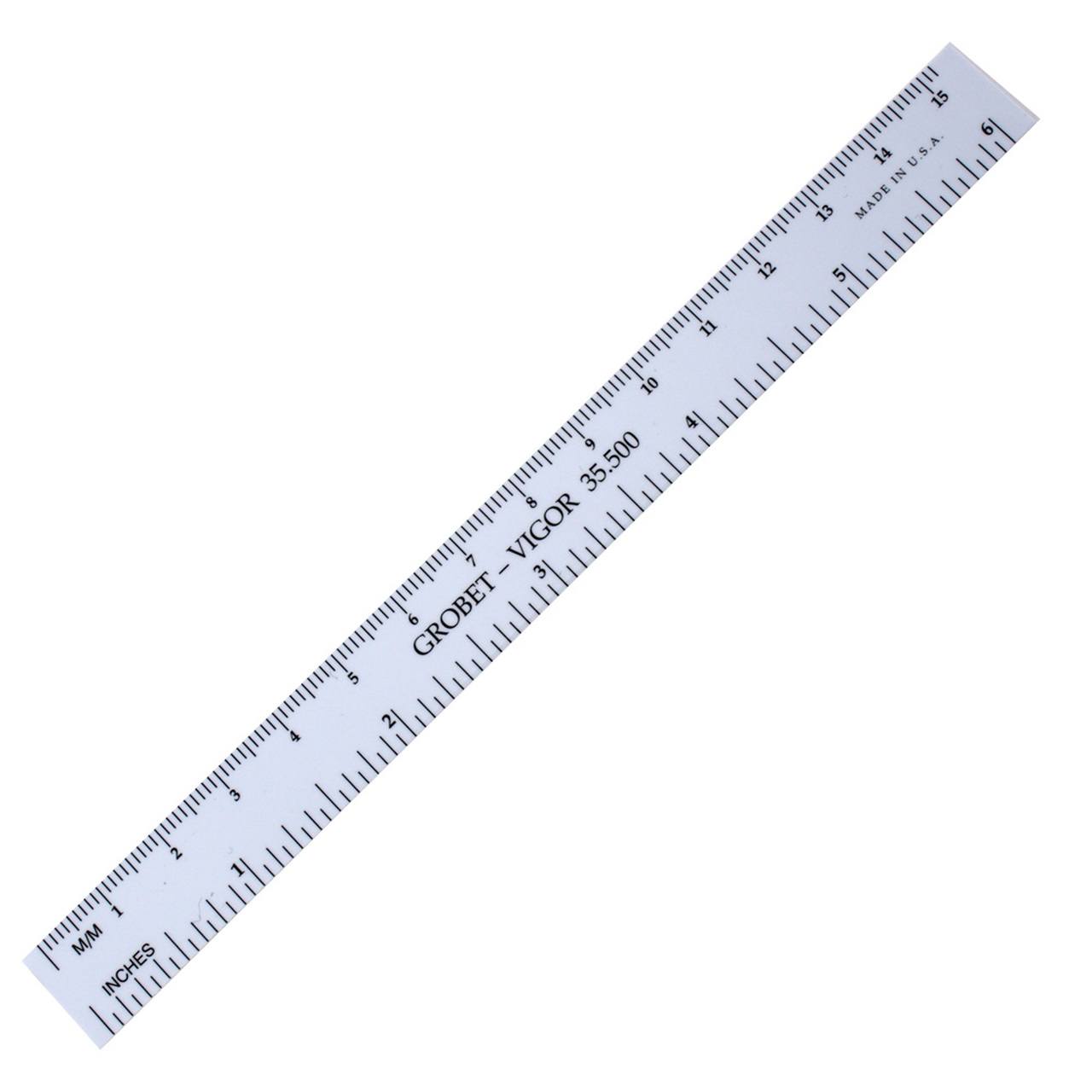
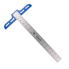
What is the name of this drawing instrument?
L Square
T Square
Ruler
Carpenter's Square
It is used to draw horizontal line.
T Square
30x60 triangle
Protractor
Divider

What is the name of this drawing instrument?
Hip Curve
Flexible Curve
French Curve
Road Curve

The following are the advantages of using a Mechanical Pencil.
Consistent line marking.
Sharpening is not necessary.
Inexpensive.
Available anywhere.
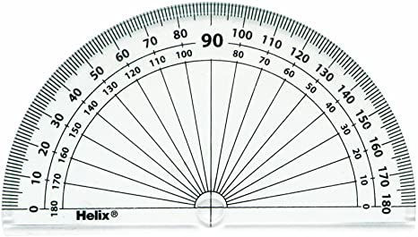
It is used to measure angles.
Triangle
Ruler
Divider
Protractor
It is used to draw common shapes, symbols and figures.
Lettering Guides
Templates
Stencils
Pencils
It is used to draw circles and arcs.
Divider
Ruler
Compass
Protractor

What is it called??
Protractor
Compass
Graphite pencil
The 60

What is it called??
Protractor
The 45
The 60
Graduated ruler
A drawing tool used to draw horizontal lines and serve as guide for triangle.
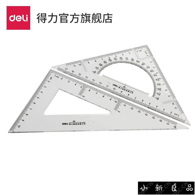
An instrument used for drawing vertical and oblique lines.
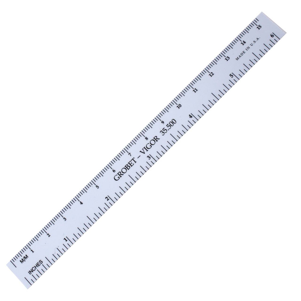
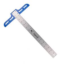
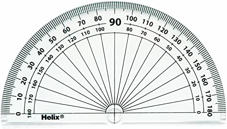
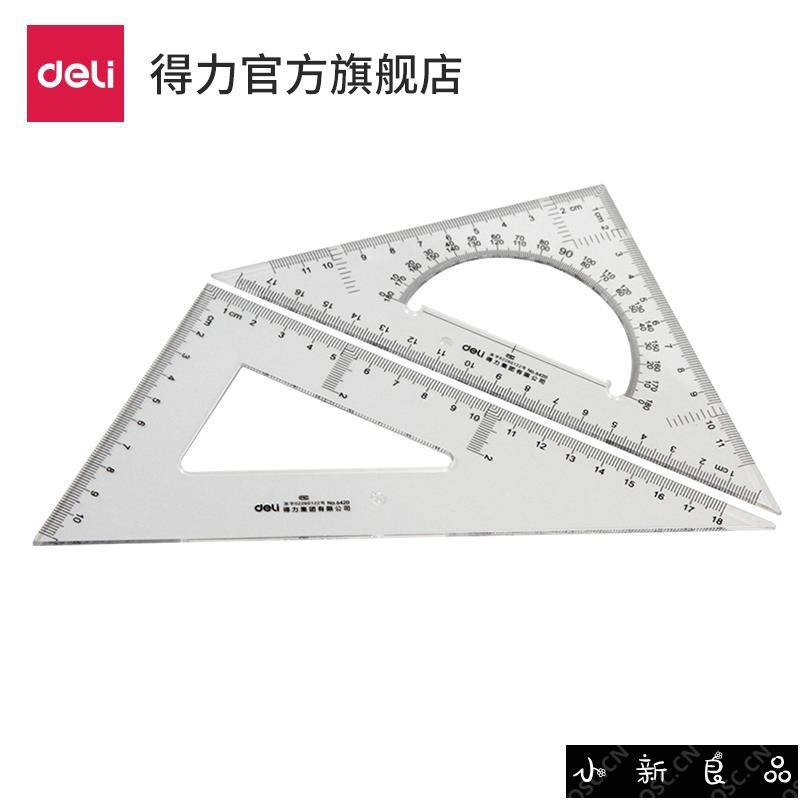
The best instrument used for dividing lines or distance into equal parts.
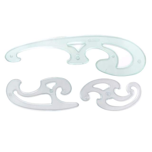
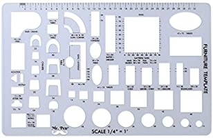
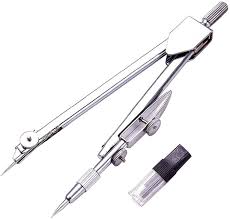
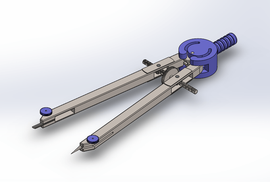
It is used in setting a line degree angle.
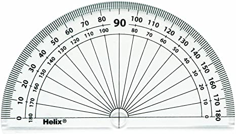
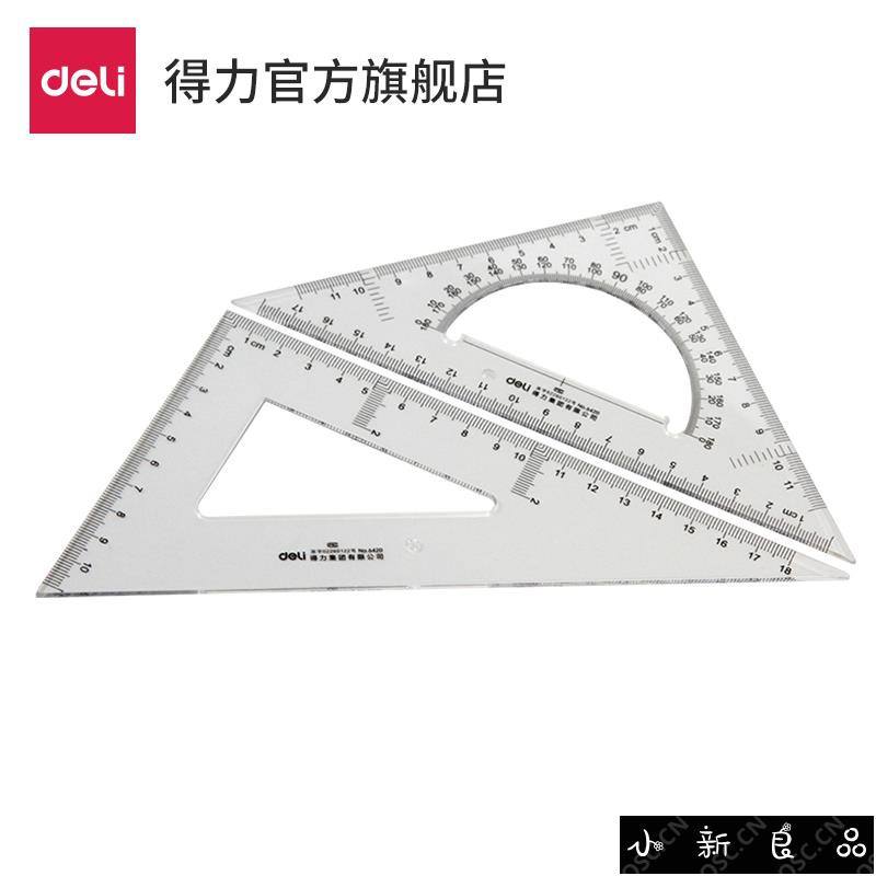
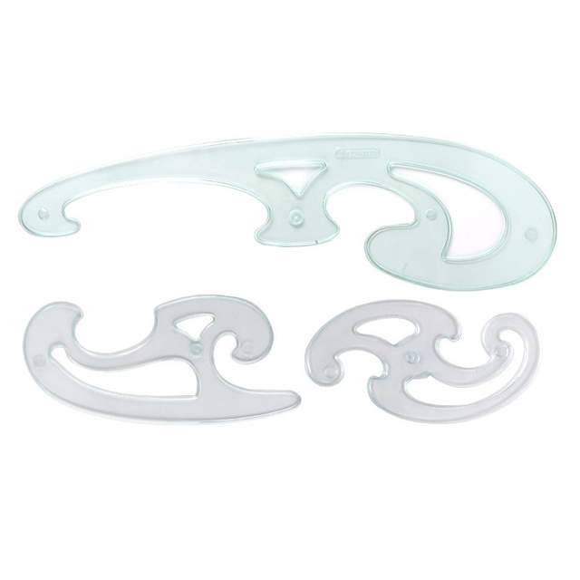
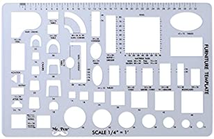
A ruler that has a 3-lobed cross-section with 6 different types of scales on the edges (2 on each face) used for measuring and preparing scale drawings such as blueprints and maps. It is also called an architect's scale.


Which is the enlarge sale?
1:1
1:5
1:100
2:1


What type of Sketch is this
Perspective
Oblique
Isometric
Multi View

What type of Sketch is this
Perspective
Oblique
Isometric
Multi View

What type of Sketch is this
Perspective
Oblique
Isometric
Multi View

What type of Sketch is this
Perspective
Oblique
Isometric
Multi View

What type of Sketch is this
Perspective
Oblique
Isometric
Multi View
How is a visible line represented in an engineering drawing?
Continuous thick lines
Equal dashed lines
Long dashed, short dashed lines
I don't know yet
How is a centre line represented in an engineering drawing?
Continuous thick lines
Equal dashed lines
Long dashed, short dashed lines
I don't know yet
How is a hidden detail represented in an engineering drawing?
Continuous thick lines
Equal dashed lines
Long dashed, short dashed lines
I don't know yet
Name two vital pieces of information that should be included in a title block?
Name & Date
Projection symbol & Scale
Materials & Drawing Number
I don't know yet
If a drawing is created to the actual size of the object what scale would be used in the title block?
1:1
1:2
2:1
I don't know yet
If a drawing is created twice the size of the actual object what scale would be used in the title block?
1:1
1:2
2:1
I don't know yet
If a drawing is created half the size of the actual object what scale would be used in the title block?
1:1
1:2
2:1
I don't know yet
Why must all the rules of an engineering drawing be followed precisely?
To ensure a consistent approach is used and British standards are met
To ensure the drawing looks good
To ensure an inconsistent approach is taken and British standards are not met
I don't know yet
Using a computer to draw is called
graphic drawing
digital drawing
computer drawing
technology drawing
A/n ____________ Line represents the edges of the object
Object
Center
Hidden
Extension

What Line-Type is this?
center line
hidden line
construction line
phantom line
The standard 3 views are top, front, & left.
true
false

What type of pictorial sketch is most like the human eye sees?
Perspective
Cavalier oblique
Isometric
Engineering

What type of line is drawn lightly and helps guide the sketch?
Extension lines
Object lines
Hidden line
Construction line
Use as guide in drawing horizontal lines.
Protractor
Rule
Scale
T-Square
Triangles are used as guide in drawing vertical and inclined lines.
True
False
Choose the 3 major views of an object.
Top view
Front view
Rear view
Right side view
Bottom view

What will be the top view of the given isometric object?


Which views most commonly get drawn for multiview drawings?
front, rear, right
front, top, left
front, top, right
front, top, right, left, rear, bottom
How many views does EVERY object have?
1
3
4
6
How many views have to be drawn to completely show a cylinder as a multiview drawing?
1
2
3
4
Which of these is the correct BS symbol for First Angle Projection?
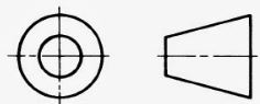
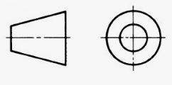
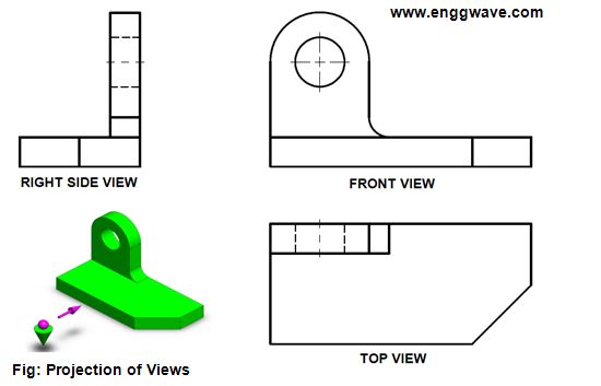
What projection is this object drawn in?
First Angle
Third Angle
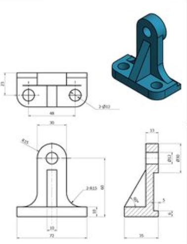
What projection is this object drawn in?
First Angle
Third Angle

Which orthographic view is the arrow pointing to? Be sure to pay close attention to the direction of the arrow.


Which orthographic view is the arrow pointing to? Be sure to pay close attention to the direction of the arrow.


Which orthographic view is the arrow pointing to? Be sure to pay close attention to the direction of the arrow.


Which orthographic view is the arrow pointing to? Be sure to pay close attention to the direction of the arrow.


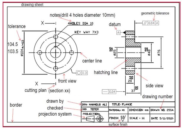
What kind of view is shown on the right hand side?
Isometric
Section
Assembly
Oblique
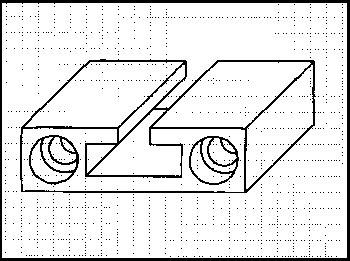
What is the correct term for this drawing type?
Isometric
3D
Orthographic
Oblique
What does ISO stand for when looking at conventional drawings?
Institute for Standards
International Science Organisation
International Standards Organisation
Independent Standards Organisation

If the side of an object has been drawn at 45 degrees to the front face, which type of drawing do we have?
Isometric
Orthographic
Oblique
Perspective

What Line-Type is this?
center line
dimension line
extension line
phantom line
The system of measurement that is used in Australia is?
Imperial
Republic
Metric
Pounds
Which type of projection is used to create multiview drawings?
orthographic
photographic
pictorial
technical
What is the 45 degree line used to project views across called?
auxiliary
miter
profile
projection

Which of the following constructions is illustrated in the diagram?
A square
Irregular curve
Circle in isometric
Circle in perspective

The drawing type shown in the figure is:
Part
Drawing
Assembly
Presentation

Center Line
Cutting Plane Line
Object Line
Hidden Line

Section Line
Phantom Line
Dimension Line
Extension Line

Border Line
Phantom Line
Dimension Line
Extension Line

Center Line
Cutting Plane Line
Object Line
Hidden Line

Which drawing below shows the Top View?


Which diagram below shows the right view of this object?


Recognize the view for the given isometric figure.
Top view
Right side view
Left side view

Find the side elevation for the solid shown...


Find the front elevation for the solid shown...


Find the plan view for the solid shown...


The correct plan of the solid is


Which is NOT intended of technical drawings?
Visualization
Communication
Documentation
Accreditation