
 Worksheets
eng drw1
Total questions: 37
Worksheet time: 19mins
Manufacturing is principally concerned with ensuring........
functionality
interchangeability
quality
acceptable tolerance
all of these
True
To show all the information that is needed to read the drawing
To show names and units of measurements
To show how to manufacture the part
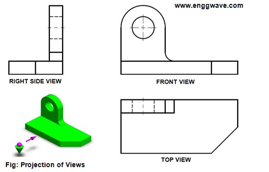
What projection is this object drawn in?
First Angle
Third Angle
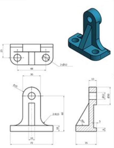
What projection is this object drawn in?
First Angle
Third Angle

What kind of line is shown?
extension line
leader line
dimension line

What kind of line is shown?
extension line
dimension line
leader line

What kind of line is shown?
extension line
leader line
dimension line

What does the symbol mean?
radius
hole
diameter
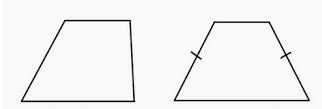
Which dimensioning is better?


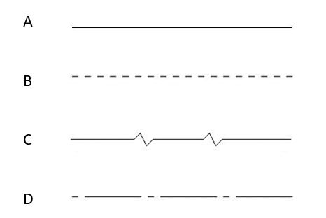
6. Which of the following represents a centre-line?
A
B
C
D
Which of these is the correct BS symbol for First Angle Projection?
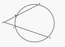
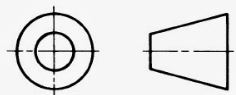
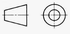
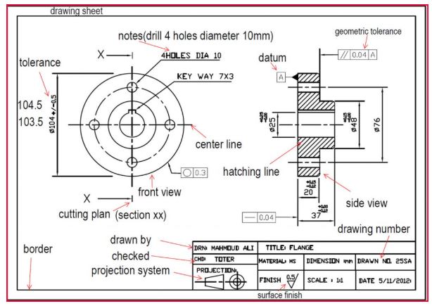
What kind of view is shown on the right hand side?
Isometric
Section
Assembly
Oblique
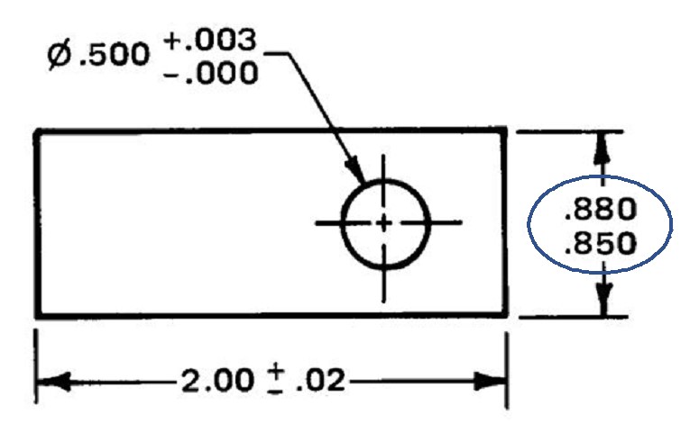
What type of tolerance is assumed when none is stated?
Limit dimensions
Bilateral
Unilateral
General
What is the total tolerance for this dimension?
1.80
1.70
1.75
0.10

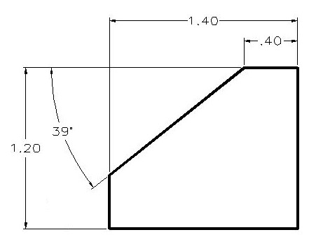
Which of the following views of the part shows a full section view.


What type of tolerance is circled in this drawing?
Limit dimensions
Bilateral
Unilateral
General

Which type of engineering drawing is shown?
Detailed Component Drawing
General Assembly Drawing
Sub-Assembly Drawing

Which type of engineering drawing is shown?
Detailed Component Drawing
General Assembly Drawing
Sub-Assembly Drawing

Why are Section Views used on engineering drawings?
They represent an inverted view of the part.
They are used to apply dimensions to.
They combine 2 orthographic views in to one view.
They explain a part in better detail that may be difficult to visualize in an orthographic view.

What type of hole is called out in this image?
Radius
Counterbore
Countersink
Spotface

What type of view is in the picture shown?
Section View
Detail View
Plan View
Isometric View
Which of the following views of the part shows a half section view.

What is shown highlighted?
Title Block
Bill of Materials
Tolerance Block
Leader Line

What is the name of the circles that label parts or components in a technical drawing?
Balloons
Leader Lines
Tolerance
Subassembly

The mistake in this dimension label is :
Extension lines should not cross the dimension lines
Mitter lines should not cross the extension lines
Leader lines should not cross the dimension lines
Extension lines, leader lines should not cross the dimension lines

what type of fit is this
Clearance
Interference
Transition
Nominal
In the ISO Hole based tolerance system, the fit for the Hole is signified by:
Upper case Letters
Lower Case Letters
Mixture of both upper and lower case letters
No letters at all
Why are tolerances given to parts?
To show how the part is made
To ensure correct function of mating parts
To reduce cost of the assembly
To have a range of sizes

What do the dashed lines represent on a part drawing?
Small features.
Holes.
Dimension lines.
Hidden surfaces or edges.

What type of hole is called out in this image?
Radius
Counterbore
Countersink
Spotface

what type of fit is this
clearance
interference
transition
nominal
In the ISO Hole based tolerance system, the fit for the Shaft is signified by:
Upper case letters
Lower case letter
mixture of upper and lower case letters
no letters at all

What type of hole best describes this image?
spotface
countersink
counterbore
diameter

what type of fit is this
clearance
interference
transition
nominal
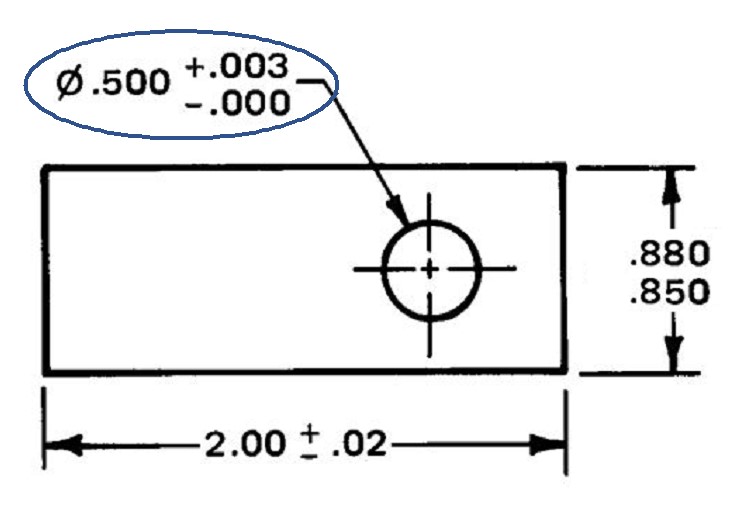
What type of tolerance is circled in this image?
Limit dimensions
Bilateral
Unilateral
General

