
 Worksheets
Harper_ELT140_FinalExam
Total questions: 38
Worksheet time: 20mins
Why PLC is developed.
To replace Computer systems.
To replace Relay system.
PLC is abbreviated as___________
Programmable Logic Controller
Programmable Logic Computer
_________ programming Language is used for PLC
Java
C Language
Ladder Diagram
All of the above
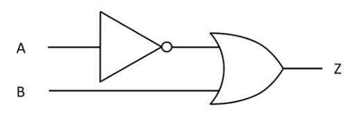
What is the Logic Expression for this circuit?
Z = NOT (A AND B)
Z = NOT (A OR B)
Z = (NOT A) AND B
Z = (NOT A) OR B


What will the circuit's output be?
1
0
A + 1 =
1
0
A
A pair of smelly sneakers
~A


In this circuit, if A and B were both 0, what would R be?
0
1

How is the circuit connected for Boolean Expression + (addition)
Series
Parallel
Combination
Open or not connected
________ Ladder diagram for AND Gate.


NC contact can be used to satisfy ________gate condition.
NOT
OR
AND
NOR

The output Y1 turns ON when:
X1 is on AND either X2 OR X3 is off
X1 is on AND either X2 OR X3 is on
X1 is on OR both X2 OR X3 is on
X1 is off AND either X2 OR X3 is on
Delay ON timer is a short time that
Will start as soon as program start.
Will start at any time during program.
Will turn the output OFF after a certain DELAY
Will turn the output ON after a certain DELAY
Delay OFF timer is a short time that
Will start as soon as program start.
Will start at any time during program.
Will turn the output OFF after a certain DELAY
Will turn the output ON after a certain DELAY
____________ track the number of events that take place in a process
On Delay Timer
Off Delay Timer
Up/Down Counter
Internal Memory
The______ counter that counts the events that has happened and decrements the counted number by one count.
Up Counter
Down Counter
Weekly Counter
Hourly Counter
_________ is the brain of the PLC
Computer
CPU
Memory
Input Device
_________ is the input device of PLC
Keyboard
Sensors
Hard disc
Monitor
The Inputs of PLC is represented as _____________in ladder diagram.
Switches
Actuators
The vertical lines in a ladder diagram is called as ______________
Rungs
Rail
The horizontal lines in a ladder diagram is called as ______________
Rungs
Rail

Identify the symbol shown by the image?
Normally Closed Contact
Normally Open Contact
Relay Coil
Normally open pushbutton

Identify the symbol shown by the image?
Normally Closed Contact
Normally Open Contact
Relay Coil
Normally open pushbutton

What is this symbol called?
Output coil
Normally Open contact
Normally Closed contact
Which type of PLC would be able to except additional input cards after it has been installed?
fixed
modular
standalone
portable

What is the name of the part marked with red in the figure?
Power Supply connection
Output connection
Control Panel
Input connection
How many binary bits are in a byte?
1
2
8
16
A discrete input module which can be interfaced is ___________
Horn
push buttons
contactor
Pilot lamp
Which type of memory stores the PLC operating system?
RAM
ROM
GOAT
USB
________ is used for circuit that is able to hold the output energized.
Timer
Latching
The Inputs of PLC is represented as _____________in ladder diagram.
Switches
Actuators
Is an electrically operated switch. Current flowing through the coil creates a magnetic field, which attracts a lever and changes the switch contacts.
Normally open pushbutton
Normally closed pushbutton
Relay
Emergency switch
What is the default value of timers
Seconds
Milliseconds
Hours
Minuets
Field devices refers to what?
Input devices only
Load devices only
Output devices only
All devices physically wired to the PLC
In PLC operation ___________ checks the status at the input side
Input scan
Output scan
Program scan
None of the above

