
 Worksheets
Microwave Module 4 Subtopic 2 Part 2
Total questions: 59
Worksheet time: 31mins
In Microwave Transistors:
The primary differences between standard lower frequency transistors and microwave types are internal 1. _ and 2. _.
1. geometry
2. packaging
1. circuit design
2. receiver systems
1. transistors
2. gain
1. attenuation
2. receive signal level
In Microwave Transistors:
To reduce internal inductances and capacitances of transistor elements, special chip configurations known as ___ are used.
geometries
transistors
integrated circuits
circuits
In Microwave Transistors:
__ permit the transistor to operate at higher power levels and at the same time minimize distributed and stray inductances and capacitances.
geometries
transistors
integrated circuits
circuits
In Microwave Transistors:
The ___ , a type of JFET using a Schottky barrier junction, can operate at frequencies above 5 GHz.
GaAs MESFET
Silicon MOSFET
MOSFET
BJT
In Microwave Transistors:
The GaAs MESFET, a type of JFET using a Schottky barrier junction, can operate at frequencies above ___.
5 GHz
5 MHz
4 kHz
3 kHz
In Microwave Transistors:
A _ is a variant of the MESFET and extends the range beyond 20 GHz by adding an extra layer of semiconductor material such as AlGaAs.
high electron mobility transistor (HEMT)
low electron mobility transistor (LEMT)
high electron mobility transmitter (HEMT)
low electron mobility transistor (LEMT)
In Microwave Transistors:
A high electron mobility transistor (HEMT) is a variant of the MESFET and extends the range __ by adding an extra layer of semiconductor material such as AlGaAs.
beyond 20 GHz
below 20 GHz
beyond 10 GHz
below 10 GHz
In Microwave Transistors:
A high electron mobility transistor (HEMT) is a variant of the MESFET and extends the range beyond 20 GHz by adding an extra layer of semiconductor material such as _.
AlGaAs
GaAs
AlAs
AlJaMeS
In Microwave Transistors:
A popular device known as a __ is making even higherfrequency amplification possible in discrete form and in integrated circuits. It can operate up to 200 GHz.
high electron mobility transistor (HEMT)
low electron mobility transistor (LEMT)
hetero-junction bipolar transistor (HBT)
hetero-junction transistor (HJT)
In Microwave Transistors:
hetero-junction bipolar transistor (HBT) can operate up to __
200 GHz
200 MHz
100 kHz
300 GHz
Small Signal Amplifiers
A low-noise transistor with a gain of about ___ is typically used as a microwave amplifier.
10 to 25 dB
15 to 20 dB
5 to 10 dB
20 to 30 dB
Small Signal Amplifiers
A ___ transistor with a gain of about 10 to 25 dB is typically used as a microwave amplifier.
low-noise
high-noise
BJT
FET
Small Signal Amplifiers
Most microwave amplifiers are designed to have input and output impedances of _.
50 Ω
60 Ω
40 Ω
30 Ω
Small Signal Amplifiers
The transistor is biased into the linear region for __ operation.
class A
class B
class C
class D
Small Signal Amplifiers
__ are used in the collector supply lead for further decoupling.
Ferrite beads (FB)
Ferrous Beads (FB)
Feed beads (FB)
Ferric beads (FB)
Small Signal Amplifiers
Ferrite beads (FB) are used in the collector supply lead for further __.
decoupling
coupling
attenuation
gain
Small Signal Amplifiers
A common ____ amplifier is one that incorporates two or more stages of FET or bipolar transistors made on a common chip to form a multistage amplifier.
monolithic microwave integrated circuit (MMIC)
high electron mobility transistor (HEMT)
Geometries
hetero-junction bipolar transistor (HBT)
Small Signal Amplifiers
A common monolithic microwave integrated circuit (MMIC) amplifier is one that incorporates two or more stages of FET or bipolar transistors made on a common chip to form a ___.
multistage amplifier
single amplifier
cascade amplifier
signal amplifier
Small Signal Amplifiers
monolithic microwave integrated circuit (MMIC) chip also incorporates _ for biasing and small bypass capacitors.
resistors
capacitors
inductors
filters
Small Signal Amplifiers
Monolithic microwave integrated circuit (MMIC), Physically, these devices look like transistors.
True
False
Small Signal Amplifiers
Another form of MMIC is the __, which combines an amplifier IC connected to microstrip circuits and discrete components.
hybrid circuit
integrated circuit
quad two input IC
two input IC
In Power Amplifiers
A typical __ microwave power amplifier is designed with microstrip lines used for impedance matching and tuning.
class A
class B
class C
class D
In Power Amplifiers
Input and output impedances are __.
50 Ω
40 Ω
30 Ω
20 Ω
In Power Amplifiers
Typical power-supply voltages are 1._, 2._, and 3._ volts.
1. 12
2. 24
3. 28
1. 10
2. 26
3. 30
1. 8
2. 21
3. 26
1. 14
2. 22
3. 23
In Power Amplifiers
Most power amplifiers obtain their bias from __ sources.
constant-current
constant-voltage
constant-gain
constant-power
In Power Amplifiers
A single-stage FET power amplifier can achieve a power output of __ in the high UHF and low microwave region.
100W
200W
100A
200V
In Power Amplifiers
A single-stage FET power amplifier can achieve a power output of 100W in the ___.
high UHF and low microwave region
low UHF and high microwave region
mid UHF and high microwave region
low UHF and mid microwave region
In Solid State Devices Efficiency:
What doesn't get converted to goes into __;
heat
energy
power
storage
In Solid State Devices Efficiency:
heat is almost universally a bad by-product of energy conversion.
True
False
In Solid State Devices Efficiency:
In microwave engineering, we are interested in converting 1. _ power to 2. _ power.
1. DC
2. RF
1. RF
2. DC
1. AC
2. HF
1. HF
2. AC
In Solid State Devices Efficiency:
The lower the power amp efficiency, the longer the cell phone can operate.
True
False
In Solid State Devices Efficiency:
Some _ power amplifiers have been known to exceed _ efficiency.
Class-E,
80%
Class-A,
90%
Class-B,
70%
Class-D,
80%
In Solid State Devices Efficiency:
Maximum efficiency of a microwave device is a function of frequency, temperature, input drive level, load impedance, bias point, device geometry, and intrinsic device characteristics.
True
False
In Solid State Devices Efficiency:
It is truly a multidimensional problem! You can determine the maximum efficiency under different conditions using __.
load pull
supply pull
load push
supply push
In Solid State Devices Efficiency:
Note that laws of thermodynamics won't allow 100% efficiency, no matter how you calculate it.
True
False
In Solid State Devices Efficiency:
Some switching voltage regulators can convert one voltage to another with an amazing __ efficiency.
90%
80%
70%
60%
Five Measures of Efficiency
1. Drain efficiency
2. Power added efficiency
3. Total efficiency
4. Amplifier efficiency
5. wall plug efficiency
1. Source efficiency
2. added efficiency
3. Load efficiency
4. Gate efficiency
5. Antenna efficiency
1. Receiver efficiency
2. Part efficiency
3. Load efficiency
4. Gate efficiency
5. Antenna efficiency
1. Source efficiency
2. Transmitter efficiency
3. Load efficiency
4. Gate efficiency
5. Antenna efficiency
Five Measures of Efficiency:
__ it gets its name from FET devices, where the primary terminal where DC power is supplied is the drain.
Drain efficiency
Power added efficiency
Total efficiency
Amplifier efficiency
wall plug efficiency
Five Measures of Efficiency:
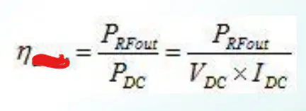
__ efficiency is the ratio of output RF power to input DC power:
Drain efficiency
Power added efficiency
Total efficiency
Amplifier efficiency
wall plug efficiency
Five Measures of Efficiency:
__ is similar to drain efficiency, but it takes into account the RF power that is added to the device at its input, in the numerator.
Drain efficiency
Power added efficiency
Total efficiency
Amplifier efficiency
wall plug efficiency
Five Measures of Efficiency:
__ is the most-accepted figure-of-merit to use to compare single devices.
Drain efficiency
Power added efficiency
Total efficiency
Amplifier efficiency
wall plug efficiency

Five Measures of Efficiency:
Drain efficiency
Power added efficiency
Total efficiency
Amplifier efficiency
wall plug efficiency
Five Measures of Efficiency:
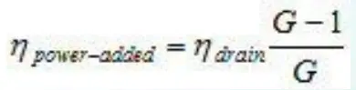
In a theoretical sense, an amplifier with infinite gain will have power added efficiency equal to drain efficiency.
True
False
Five Measures of Efficiency:
For a real amplifier, PAE will always be less than drain efficiency, but once you get to 1. __ gain or so, the two quantities become very close in value because input power will be less than 2. __ of output power (30 dB gain is 1000 in linear scale).
1. 30 dB
2. 0.1%
1. 40 dB
2. 0.01%
1. 30 dB
2. 0.001%
1. 20 dB
2. 10%
1. 40 dB
2. 1%
Five Measures of Efficiency:
You can express PAE in terms of drain efficiency, you will get:
Di ko alam kung pano gagawing tanong to, note nyo nalang
Ako si Jakob
Five Measures of Efficiency:
For an amplifier with 30 dB gain, PAE and drain efficiency differ by just 0.1 percent (999/1000).
True
False
Five Measures of Efficiency:
The maximum possible power-added efficiency of a device always increases with frequency.
True
False
Five Measures of Efficiency:
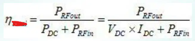
sometimes called overall efficiency, gives a more-complete picture of the ratio of output power to both types of input power (DC and RF):
Drain efficiency
Power added efficiency
Total efficiency
Amplifier efficiency
wall plug efficiency
Five Measures of Efficiency:
is the measure that makes the most sense from a thermodynamic point of view. But PAE is still the most popular measure in the microwave community.
Drain efficiency
Power added efficiency
Total efficiency
Amplifier efficiency
wall plug efficiency
Five Measures of Efficiency:
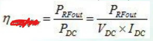
is the ratio of RF output power to DC input power, and is the best for a multi-stage amplifier.
You can assume this is a "peak" measurement if you are considering a pulsed amplifier.
is the accepted measurement of an amplifier product.
Drain efficiency
Power added efficiency
Total efficiency
Amplifier efficiency
wall plug efficiency
Five Measures of Efficiency:
In practice, for an amplifier with high gain: __ efficiency, _ and _ efficiency will be close enough to be equal.
Drain efficiency
Power added efficiency
Total efficiency
Amplifier efficiency
wall plug efficiency
Five Measures of Efficiency:
Drain efficiency
Power added efficiency
Total efficiency
Amplifier efficiency
wall plug efficiency
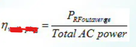
Five Measures of Efficiency:
By wall plug efficiency, we mean if you compared average RF output power to exact measured power that is consumed by the product from its AC wall plug, ignoring the effect of RF input power.
Drain efficiency
Power added efficiency
Total efficiency
Amplifier efficiency
wall plug efficiency
Benchmarks:
- L Band
- X-Band
- Wideband
- Ku-Band
- Q and W-Band
- Ka-Band
- D Band
- K Band
Benchmarks:
Silicon LDMOS devices are offered that achieve 60% drain efficiency, with GaN HEMT devices lately looking like they are even better. Run at Class E you can exceed 80% drain efficiency
L Band
X-Band
Ku-Band
Wideband
Ka-Band
Benchmarks:
MESFET amplifiers with 10% bandwidth can exceed 30% efficiency at ___. GaAs pHEMT amplifiers can exceed 40% PAE at ___, GaN HEMT can break 50%. TWTs routinely delivers 60% efficiency
L Band
X-Band
Ku-Band
Wideband
Ka-Band
Benchmarks:
the more the bandwidth, the lower the efficiency, because you can't just hit the best load over that much bandwidth.
Distributed amplifiers are notoriously inefficient, because the devices don't all get the same voltage: some are ready to burn our and some are coasting!
A solid-state amplifier that works from 2-18 GHz will have less than 10% PAE.
L Band
X-Band
Ku-Band
Wideband
Ka-Band
Benchmarks:
you might read about __ amplifiers that hit 30% efficiency on a good day, but don't expect to beat 20% with COTS part.
L Band
X-Band
Ku-Band
Wideband
Ka-Band
Benchmarks:
these frequencies, GaN HEMT has already hit 30% PAE at device level and close to 20% amplifier efficiency. COTS parts at these frequencies all suck, don't even go there.
Q and W-band
X-Band
Ku-Band
Wideband
Ka-Band

