
 Worksheets
SMJE 2133 Voltage Regulator
Total questions: 20
Worksheet time: 18mins
Line regulation is a measure of how constant the output voltage is for a given change in the input voltage.
True
False
Load regulation depends on the amount of power dissipated in the load.
True
False
Two types of linear regulator are series and bypass.
True
False
Current limiting is used to protect the external bypass transistor.
True
False
In the case of line regulation,
when the temperature varies, the output voltage stays constant
when the output voltage changes, the load current stays constant
when the input voltage changes, the output voltage stays constant
when the load changes, the output voltage stays constant
In the case of load regulation,
when the temperature varies, the output voltage stays constant
when the input voltage changes, the load current stays constant
when the load changes, the load current stays constant
when the load changes, the output voltage stays constant
All of the following are parts of a basic voltage regulator except
control element
sampling circuit
voltage-follower
error detector
The basic difference between a series regulator and a shunt regulator is
the amount of current that can be handled
the position of the control element
the type of sample circuit
the type of error detector
In a basic series regulator, Vout is determined by
the control element
the sample circuit
the reference voltage
the sample circuit and reference voltage
The main purpose of current limiting in a regulator is
protection of the regulator from excessive current
protection of the load from excessive current
to keep the power supply transformer from burning up
to maintain a constant output voltage
In a linear regulator, the control transistor is conducting
a small part of the time
half the time
all of the time
only when the load current is excessive
In a basic shunt regulator, VOUT is determined by
the control element
the sample circuit
the reference voltage
the sample circuit and reference voltage
A single-phase transformer with a voltage regulation of 4% has a secondary terminal voltage of 115.4 volts at full load current. Calculate its no-load terminal voltage when the load is removed.
120V
119V
121V
118V
Two power supplies A and B are available in the market. Power supply A has a no-load and full-load voltages of 30V and 25V respectively whereas these values are 30V and 29V for power supply B. Which is better power supply?
Power supply A
Power supply B
The input of a certain regulator increases by 3.5 V. As a result, the output voltage increases by 0.42 V. The nominal output is 20 V. Determine the regulation in %/V.
0.7%/V
0.4%/V
0.6%/V
0.5%/V
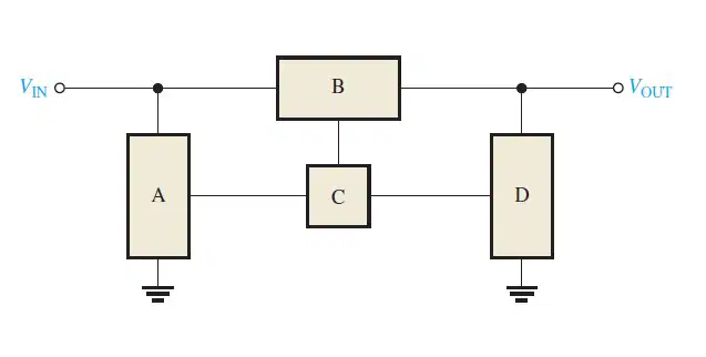
Label the functional blocks for the voltage regulator in Figure
A: Reference voltage, B: Control element, C: Error detector, D: Sample circuit
A: Sample circuit, B: Control element, C: Error detector, D: Reference voltage
A: Error detector, B: Sample circuit, C: Reference voltage, D: Control element
A: Control element, B: Reference voltage, C: Error detector, D: Sample circuit

Calculate the value of Vout
(a)
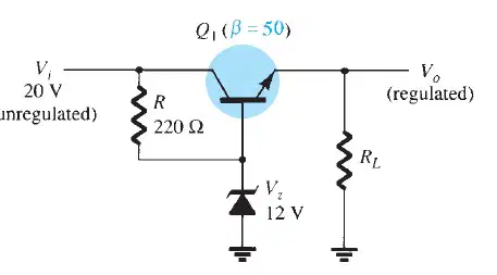
Calculate the value of Vo if VBE=0.7V
(a)
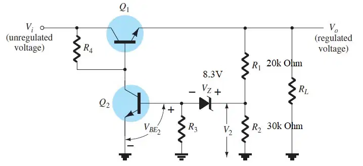
Calculate the value of Vo, assume VBE2=0.7V
(a)
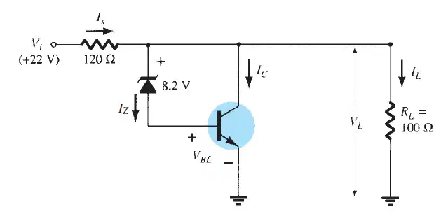
Calculate VL in the circuit, assume a practical transistor is used in the circuit
(a)

