
NEW
Font size
 Worksheets
4-12 & 4-13 PLC Classwork
Total questions: 40
Worksheet time: 2hrs 0mins
PLC stands for ___________
Programmable Logic Controller
Programmable Logic Computer
Programs Learn Computers
Program Ladder Controls
Why was the PLC developed in manufacturing?
To replace Computer systems.
To replace Relay systems.
What is the programming language used for PLCs?
Java
Python
Ladder Diagram
Block Coding
Which one is NOT an Output Device?
Motor
Solenoid
Indicator Lamp
Selector Switch

Identify the symbol shown by the image.
Normally Closed (NC)
Normally Open (NO)
Relay Coil
Motor

Identify the symbol shown by the image.
Normally Closed (NC) Pushbutton
Normally Open (NO) Pushbutton
Relay Coil
Normally Closed (NC) Switch
If two NC contacts are connected in series that satisfies _______Gate logic.
AND
NAND
OR
NOR

What the symbol function?
Normally Closed (NC)
Normally Open (NO)
Relay Coil
Lamp

Inputs X021 and X022 are shown as __________ in the ladder diagram.
parallel
series
coil
one rung

What logic function is shown here?
OR
AND
NAND
NOR
PLC implements (uses) ___________ functions by means of a program.
Arithmetic
Logic control
Which one is NOT an input for a PLC?
Solenoid
Selector Switch
Push Button
Sensor
The horizontal lines in a ladder diagram are called ______________.
Rungs
Rails
Coils

Which logic gate does this ladder logic represent?
AND gate
OR gate
NAND gate
NOR gate
An OR function used in ladder logic uses:
Normally Closed contacts in series
Normally Closed contacts in parallel
Normally Open contacts in series
Normally Open contacts in parallel
The PLC internally operates, stores, and calculates the value in _____ (meaning there are only two options, zero and one).
Binary format
Decimal format
Octal format
Hexagonal format
Which one is the correct sequence for a PLC operation?
Input scan, Logic scan & Output scan
Logic scan, Output scan & Input scan
Input scan, Output scan & Logic scan
Input scan & Output scan

Choose the symbol that is similar to this diagram.


What is the description of NO and NC?
Not Open and Not Closed
Need Open and Need Closed
Never Open and Never Closed
Normally Open and Normally Closed

What is the status of DO O1 when PB1 is pressed?
Lamp2 is turned on.
Lamp2 is turned off.
Lamp3 is turned on.
Lamp3 is turned off.

What type of logic circuit is shown here?
NOT
OR
AND
NOR
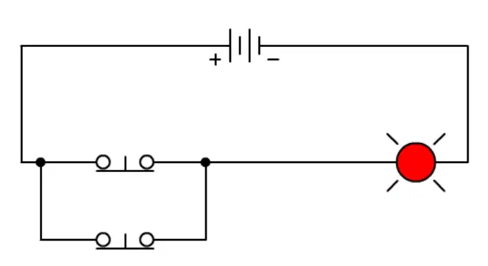
What type of logic circuit is shown here?
NAND
AND
OR
NOR

What type of logic circuit is shown here?
NOR
OR
AND
NAND
Which logic element has two or more normally open switches wired in series?
AND
OR
NOR
NAND
Which logic element has two or more normally open switches wired in parallel?
NAND
AND
OR
NOR
Which logic element has one normally closed switch wired in series with the output?
NOT
NOR
OR
AND
Which logic element consists of two or more normally closed input switches wired in parallel?
NAND
AND
OR
NOR
This is known as Exclusive OR meaning that the output turns on if one and only one of the inputs is true (not like OR which will turn an output on if both are true).
NOR
XOR
XNOR
AND
This is known as Exclusively Not OR meaning that the output turns on if both inputs are true or if both inputs are false.
NOR
XOR
XNOR
AND

Which logic gate is represented here? The operator must press both buttons at the same time for the machine to start.
AND
OR
NAND
NOR

Which logic gate is represented here? The operator can press a remote start button (away from the machine) or can press the start button on the machine.
AND
OR
NAND
NOR

Which logic gate is shown here? This provides multiple stop pushbuttons around machinery (which provides safer operations) that will stop the conveyor belt.
OR
AND
NOR
NAND

Which logic gate is represented here? An Emergency Stop pushbutton. The machine is running but if the emergency stop button is pressed, the machine will stop.
NOR
OR
AND
NOT
__________ is a hard-wired control system using switches, timers, relays, motors, wires, etc. This system has disadvantages including needing space, installation, modifications and trouble shooting.
Relay Logic
Ladder Logic
PLCs

Using the Input Memory Table, which input has been activated (pushing a button or flipping a switch)?
None of them.
PB6
PB1
PB15
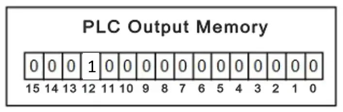
Using the Output Memory Table, which output has received voltage?
None of them.
SOL6
SOL12
SOL3

On a ladder diagram, the ____________ are shown on the left and the ______________ are shown on the right.
inputs, outputs
outputs, inputs
coils, logic gates
logic gates, coils

What is the output device shown in the diagram?
SOL1
SOL2
COM
LS1

Using the diagram, PB1 is a _____ push button and PB2 is a ______ push button.
NO, NC
NC, NO
OR, AND
AND, OR
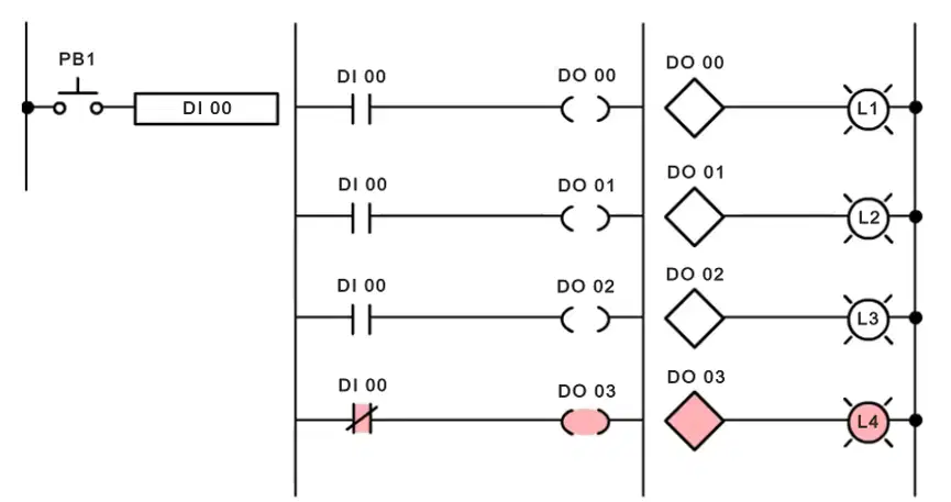
Using the diagram: Pressing PB1 will turn _____ L1, L2 and L3 and will turn _____ L4.
on, off
off, on
both, or
or, both

