
 Worksheets
Linear IC Applications-GATE-26-03-2024
Total questions: 10
Worksheet time: 9mins
The ideal OP-AMP has the following characteristics[GATE 2001-1Mark]
R i = ∞,
A V = ∞,
R o = 0
R i = 0,
A V = ∞,
R o = 0
R i = ∞,
A V = ∞,
R o = ∞
R i = 0,
A V = ∞,
R o = ∞
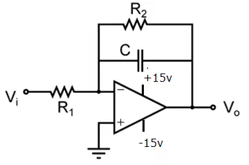
An active filter shown in the below figure. Determine DC gain and 3dB cutoff frequency of the filter R1=15.9kΩ, R2=159kΩ, C=1.0nf.[GATE-EE-2010]
40dB,3.14kHz
40dB,1kHz
20dB,6.28kHz
20dB,1kHz

Given that the Op-Amp is ideal, the output voltage Vo is [GATE-EE-2010]
4 V
6 V
7.5 V
12.12 V

If the input to the circuit of figure is a sine wave the output will be[GATE-1990-2 Marks]
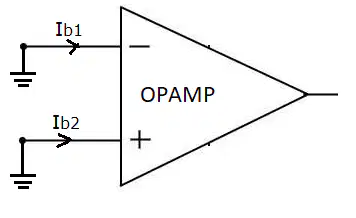
For the op-amp shown in the figure, the bias currents are Ib1= 450 nA and Ib2=350 nA. The values of the input bias current (IB) and the input offset current (If) are:[GATE-IN-2014]
(A) IB= 800 nA, If=50 nA
(B) IB= 800 nA, If=100nA
(C) IB= 400 nA, If=50nA
(D) IB= 400 nA, If=100nA

Assume that the op-amp of the figure is ideal. If Vi is a triangular wave, then V0 will be [GATE-2000: 1 Mark]

Assuming the op-amp to be ideal, the voltage gain of the amplifier shown below is [GATE-2010: 1 Mark]
−R2/R1
−R3/R1
-(R2||R3)/R1
-(R2+R3)/R1
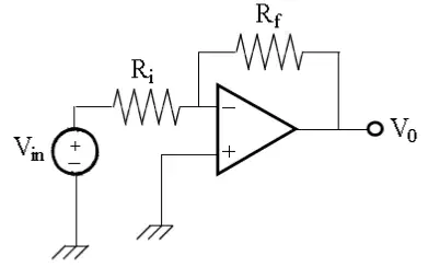
The amplifier in the figure has gain of −10 and input resistance of 50 kΩ. The values of Ri and Rf are: :[GATE-IN-2014]
(A) Ri= 500 kΩ, Rf = 50 kΩ
(B) Ri= 50 kΩ, Rf = 500 kΩ
(C) Ri= 5 kΩ, Rf = 10 kΩ
(D) Ri= 50 kΩ, Rf = 200 kΩ

The output Vo shown in the figure is close to.[GATE-IN-2017 ]
-20 V
-15 V
-5 V
0V
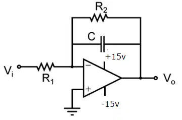
The circuit shown below is an example of a[GATE-EE-2016]
A) low pass filter
(B) band pass filter
(C) high pass filter
(D) notch filter

