
 Worksheets
تحدي physics
Total questions: 10
Worksheet time: 15mins
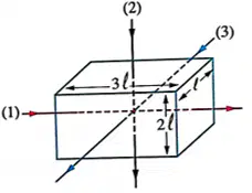
The opposite figure shows a conducting solid cuboid where each two opposite faces of the cuboid can be connected between the terminals of an electric source and the paths (1), (2) and (3) are the probable pathways of electric currents through the conductor, so in which of these paths the electric current faces the highest resistance?
Path (1)
Path (2)
Path (3)
All paths have the same resistance
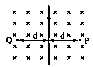
In the opposite figure, a straight wire is placed perpendicular to a uniform magnetic field of flux density B that is directed into the page. When an electric current of intensity I passes in the wire, the total magnetic flux density at point P becomes 3 B, so the net magnetic flux density at point Q is
Zero
B
2B
3 B
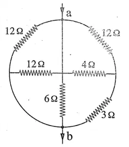
In the opposite circuit the equivalent resistance between a and b is
1 Ω
1.5 Ω
2 Ω
2.5 Ω

In the opposite circuit the ratio between the readings of the two ammeters (A1/A2 ) equals
1/2
2
4
1/4
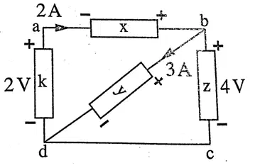
In the opposite electric circuit, the powers (Pw )x and (Pw )y are ….. respectively
4W, 12W
16W, 12W
4W, 14 W
6W, 14 W
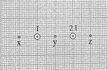
Two anti-parallel electric currents of intensities I, 2I pass through two long straight wires as shown in the opposite figure, so the correct order of magnetic flux densities at points x, y and z is
Bz>By>Bx
Bx>By>Bz
By>Bx>Bz
By>Bz>Bx
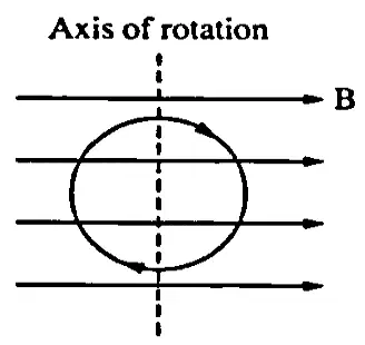
In the opposite figure, when a current-carrying circular coil was placed parallel to a uniform magnetic field of flux density B, the resultant magnetic flux density at the center of the coil was √5 " " B and when the coil rotates 90^∘, the resultant magnetic flux density at the center of the coil could be
B or 2B
B or 5 B
B or 3 B
zero or B
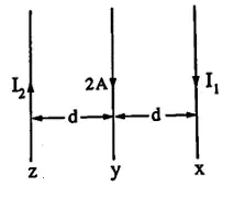
In the opposite figure, three parallel, straight
current-carrying wires are in the same plane, if you know that the magnetic force that affects a unit length of wire y is F and when the current of wire x is reversed, the force that affects a unit length of wire y becomes 1/2 F. Given that i 2 <i 1, so the ratio between the two currents i 1 / i 2 equals
3/1
4/5
5/4
1/2
A milli-ammeter gives full scale deflection when a current of 10 mA passes through its coil. If the device consists of a resistance of 0.2 Ω that is connected in parallel to a galvanometer of resistance 33 Ω, then the value of the resistance which is required to be connected in series to convert the ammeter into a voltmeter that measures a potential difference up to 10 V equals
880.2 Ω
950.3 Ω
999.8 Ω
1250.4 Ω
An electric circuit consists of a battery of negligible internal resistance, a constant resistor of 350 Ω and a galvanometer that is connected in parallel to a shunt resistance of 20 Ω. If the shunt resistance is replaced with another of 30 Ω resistance and to keep the galvanometer deflection unchanged it is required to replace the constant resistor with another of 450 Ω resistance, hence the resistance of the galvanometer equals
20 Ω
40 Ω
60 Ω
80 Ω

