
 Worksheets
Engineering drawing bank of questions
Total questions: 65
Worksheet time: 33mins
The purpose of using the smallest possible paper size for engineering drawings is
To ensure clarity and resolution
To reduce cost
To save paper
To make it easier to carry
The grid reference system used for in engineering drawings is
To measure the drawing
To add color to the drawing
To create a pattern on the drawing
To locate different elements
In an engineering drawing, the tittle block is usually located
On the side of the drawing
At the top of the drawing
In the middle of the drawing
At the bottom of the drawing
In engineering drawings, the scale is
The thickness of the lines in the drawing
The ratio between the same sizes in the drawing and reality
The color used in the drawing
The type of paper used for the drawing
In engineering drawings, the natural scale is
1 millimeter on the drawing is equal to 1 millimeter in reality
5 millimeters on the drawing are equal to 1 millimeter in reality
1 millimeter on the drawing is equal to 20 millimeters in reality
1 centimeter on the drawing is equal to 1 centimeter in reality
In engineering drawings, the enlargement scale is
1 centimeter on the drawing is equal to 1 centimeter in reality
1 millimeter on the drawing is equal to 20 millimeters in reality
5 millimeters on the drawing are equal to 1 millimeter in reality
1 millimeter on the drawing is equal to 1 millimeter in reality
In engineering drawings, the reduction scale is
1 centimeter on the drawing is equal to 1 centimeter in reality
1 millimeter on the drawing is equal to 20 millimeters in reality
1 millimeter on the drawing is equal to 1 millimeter in reality
5 millimeters on the drawing are equal to 1 millimeter in reality
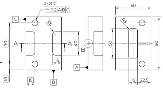
The type of engineering drawing providing detailed information about dimensions, materials, and surface finish of a single part is
Exploded view drawing
Assembly drawing
Part drawing
Isometric drawing
In an assembly drawing, a bill of materials provides information about
Tittle and creator name
Designation and part number
Scale and tittle
Projection method
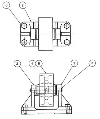
The type of drawing depicting the relative position and/or shape of a group of assembled parts is
Exploded view drawing
Assembly drawing
Isometric drawing
Part drawing
An isometric drawing provides a more realistic and comprehensive view of
Length and width
Depth and width
All three dimensions
Length and depth
In an isometric drawing, the horizontal edges are drawn at
30 degrees
90 degrees
60 degrees
45 degrees

The type of drawing showing the relationship between parts of an assembly, separated but in proper position and alignment for reassembly is
Exploded view drawing
Assembly drawing
Part drawing
Isometric drawing
A 2D drawing view provides information about
Depth
Length and width
Width
All three dimensions
The type of line used for visible edges is
Continuous thick line
Long-dashed dotted thin line
Continuous thin line
Dashed thin line
The type of line used for hidden edges is
Dashed thin line
Continuous thin line
Continuous thick line
Long-dashed dotted thin line
The type of line used for center lines and lines of symmetry is
Continuous thin line
Dashed thin line
Continuous thick line
Long-dashed dotted thin line
The projection type preferred in the USA is
Isometric projection
Third angle projection
First angle projection
Oblique projection
The projection type preferred in Europe is
Isometric projection
Third angle projection
First angle projection
Oblique projection
The maximum number of orthographic views is
4
6
5
7
The view chosen as the reference for the other views is
Front view
Right view
Left view
Top view
The view which is at the crossing of the other views is
Right view
Front view
Left view
Top view
In first angle projection, the view which is usually used to focus on the details of the object is
Left view
Right view
Front view
Top view
The main purpose of a section view in engineering drawings is
To show the external features of an object
To depict the internal features of an object
To highlight the color of an object
To display the dimensions of an object
The result of a virtual cutting plane splitting an object into two pieces is
Orthographic view
Isometric view
Detailed view
Section view
The main element of a section view is
Reference points
Dimension lines
Hatch patterns
Grid lines
In a section view, hatch patterns depend on
The weight of the object
The material of the object
The color of the object
The size of the object
A half section view is used with
Asymmetrical parts
Non-symmetrical parts
Irregularly shaped parts
Symmetrical parts
In engineering drawings, the components which are cut only transversally and not longitudinally are
Gears and pulleys
Shafts and studs
Electrical circuits
Fluid systems
The purpose of a section reference arrows is
To highlight the dimensions of the object
To mark the center of the object
To show the scale of the drawing
To indicate the direction of the section view
The ridge of uniform section in the form of a helix is called
Bolt
Thread
Nail
Screw
The largest diameter of a thread is called
Major diameter
Crest
Root
Pitch
The type of thread which advances when turned clockwise is
Buttress thread
ACME thread
Right-handed thread
Left-handed thread
The thread form designed to handle heavy forces in one direction is

Square thread

Metric ISO thread

ACME thread

Buttress thread
The screw designation M3 x 1.25 x 20 represents
Type of thread, major diameter, pitch, length
Type of thread, pitch, length
Major diameter, pitch, length
Pitch, length, type of thread
The most common type of thread for general use is

ACME thread

Metric ISO thread

Square thread

Buttress thread
The distance from a point on a screw thread to a corresponding point on the next thread is called
Pitch
Crest
Major diameter
Root
The type of thread used for power transmission and stronger than the square thread is

ACME thread

Metric ISO thread

Buttress thread

Square thread
The root of a thread represents
Distance from a point on a screw thread to a corresponding point on the next thread
Top surface of the thread
Bottom surface of the thread
Distance moved by the screw in mm
The distance travelled by a screw with a pitch of 2 mm, when you rotate it 4 times is
0.5 mm
2mm
6mm
8mm

This type of hatching is used for
Aluminum
Iron metals
Copper
Plastic

This type of hatching is used for
Aluminum
Iron metals
Copper
Plastic

This type of hatching is used for
Aluminum
Iron metals
Copper
Plastic

This type of hatching is used for
Aluminum
Iron metals
Copper
Plastic
The purpose of geometric dimensioning and tolerancing is
To communicate design intent and control variations in manufacturing processes
To analyze the color of a design
To calculate the area of a design
To determine the weight of a design
In geometric dimensioning and tolerancing, form symbols control
Color of the design
Weight of the design
Size of the design
Shape of features
In geometric dimensioning and tolerancing, position tolerance determines
The color of the design
The weight of the design
How far a feature’s location can vary from its “True Position”
The material of the design
In geometric dimensioning and tolerancing, orientation symbols control
Shape of the design
Position of surfaces, axes and planes
Location of the design
Material of the design
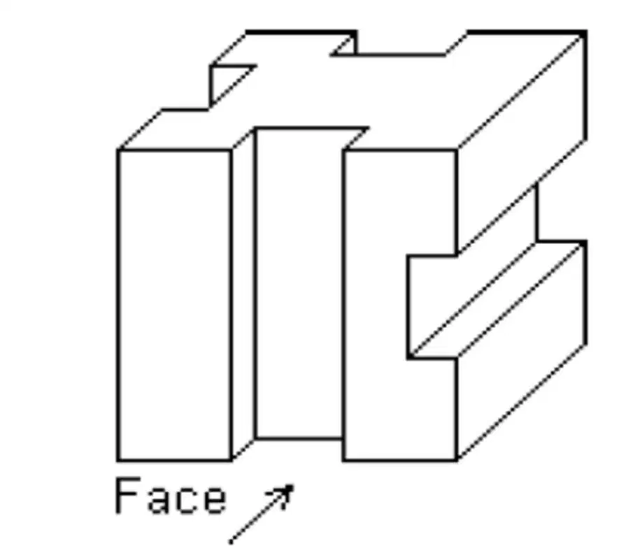
The front view of this object is
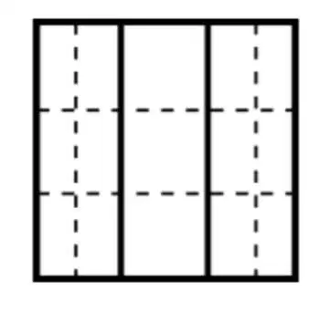
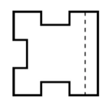
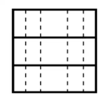
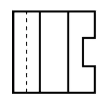
The right view of this object is
The top view of this object is

A 2 dimensions drawing depicting several assembled elements is
An assembly drawing
An isometric drawing
A part drawing
An exploded view drawing
When the drawing scale is 2/1
The drawing dimensions are twice smaller than reality
The drawing dimensions are twice bigger than reality
The real dimensions are twice bigger than drawing
The drawing dimensions are same as reality

This type of line is used to
Show the revolution and symmetrical axes
Show an edge that can not be seen
Show an edge that can be seen
Show the cut part sections

This type of line is used to
Show the revolution and symmetrical axes
Show an edge that can not be seen
Show an edge that can be seen
Show the cut part sections

This type of line is used to
Show the revolution and symmetrical axes
Show an edge that can not be seen
Show an edge that can be seen
Show the cut part sections
An offset section view is
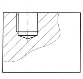


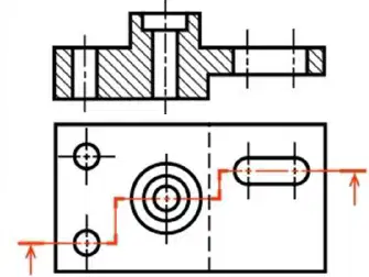
An aligned section view is


A half section view is


A partial section view is
The major diameter of a screw is
The distance between 2 consecutive crests
The diameter of the head of the screw
The largest diameter of the thread
The smallest diameter of the thread
Lines used in technical drawing are defined by
Only their nature
Their length and their width
Their width and their nature
Their length and their nature
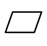
In geometric dimensioning and tolerancing, this form symbol is relative to
Straightness
Flatness
Circularity
Cylindricity
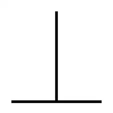
In geometric dimensioning and tolerancing, this orientation symbol is relative to
Perpendicularity
Parallelism
Circularity
Angularity

In geometric dimensioning and tolerancing, this location symbol is relative to
Perpendicularity
Symmetry
Concentricity
True position

