
 Worksheets
Ex 2º 1ª Ev TECH
Total questions: 24
Worksheet time: 18mins

The correct order of the previous algorithm is:
c, e, d, g, f, h, a, b, i.
c, f, e, d, b, h, a, g, i.
a, b, c, d, e, f, g, h, i.
c, f, e, d, a, b, h, g, i.

What problem does this algorithm solve?
Determine the average of four numbers
Determine the difference of four numbers.
Determine the sum of four numbers.
Determine the product of four numbers.

The action highlighted in green in the algorithm allows:
Write the result of the sum S.
Add the numbers A and B
Start the process
Input the numbers to operate with
What is the symbol used to indicate the START and END of a Flowchart?


What is the main error in this flowchart?
there are no processes
Too many elements
There is no end
There are no connecting arrows
Flowcharts are only used in computer science.
TRUE
FALSE
An algorithm is:
A set of ordered statements
A method to solve problems.
A short and organized process
An algorithm in which an instruction is executed one after another (with each one being the input for the next) and so on until the end of the process is a:
Conditional Algorithm
Sequential Algorithm
Constant Algorithm
Variable Algorithm
What problem does the following algorithm solve?
a) Start.
b) Enter the number 1.
c) Enter the number 2.
d) If number 1 > number 2 then Write: "The first number is greater"
e). If not Write: "The second number is greater"
f) End.
Add two numbers.
Subtract two numbers.
Fry an egg.
Compare two numbers.

What action does the symbol perform?
End
Decision
Process
Input/Output Information

What action does the symbol perform?
End
Decision
Enter information
Process

What action does this symbol perform in a flowchart?
Decision
Process
Input Information
Output Results
What is the basic structure of an algorithm?
Start, Process, End
Start, Decision, Result
Input, Process, Report
What should be the structure of an algorithm?
Problem-Purpose
Start - Decision - End
Start-Instructions-End
Input-Decision-Report
An (a) is an ordered sequence of instructions, steps, and processes that lead to the solution of a specific problem.

The main difference between an automated mechanism and a robot is:
the use of sensors to get input signals
The use of actuators to execute output signals
The use of microprocessors as the core of the control system
The use of a circuit to connect all the different parts

Analysing the difference criteria between AUTOMATED MECHANISMS and ROBOTS:
The easy programmability and the electronic processing of the information are characteristics from automated mechanisms
the sense and manipulation of its enviroment is a clear and exclusive option of automated mechanisms
The movement never will be be one of the definitory characteristic of the robots
The high complexity of tasks is a criteria that clearly differentiate robots
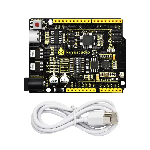
A controller board is a electronic circuit with the following components:
Processing unit, memory, input ports and output ports
Ultrasonic sensor, microprocessor, control LED and relay
Memory, automated unit, sensor and actuator
Anode, cathode, poles and switching contact
In a Control System Flowchart, sensors:
Trnasmit information from the surrounding
Receive he information from the program and send a signal to the controller
Collect information from the connected network with our automated mechanism
Receive instructions from actuators to calculate an output signal

We can describe the following control system types:
Automated mechanisms and robots
Open loop and closed loop systems
Input signal system and output signal system
Single line and complex line system
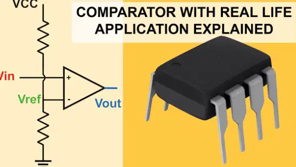
The comparator is a basic element in a control system that:
Compare the output of the system to give the best answers
Compares input signals to activate the system by the controller
Compares the input and the output signals to evaluate the higher value
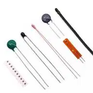
To detect variations in temperature we can use as sensor:
A NTC
A LED
A RELAY
A STD
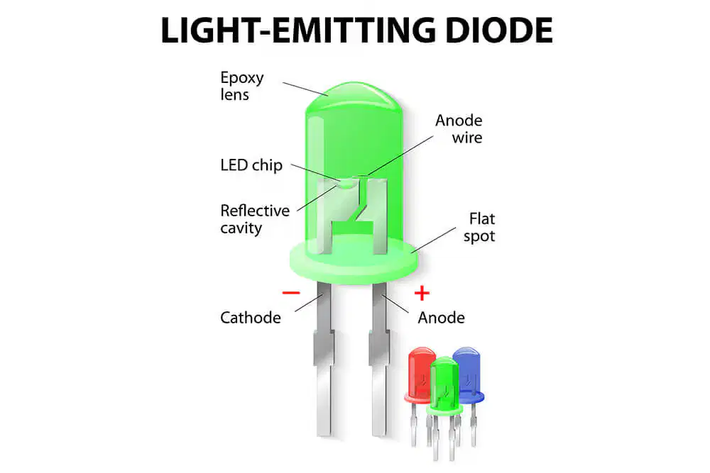
When we use a LED we must take care about:
To connect ANODE TO + AND CATHODE TO -
To connect three wires: 5V, GND and digital pin
To connect in series with a 20 Ω resistor to withstand the current
not connect directly with an Arduino
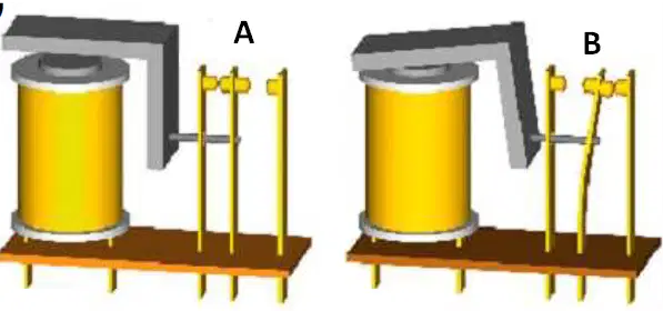
In the figure we can identify:
A relay, where the current is circulating in stage 2 but no in stage 1
A LED with the poles to connect and emiting a yellow light
A light-dependent resistor which show circuit variation depending of received light
A microprocessor where instructions are transmitted contacting in alternate sides

