
 Worksheets
DEI30073 REVISON CLASS
Total questions: 21
Worksheet time: 28mins
For higher accuracies _________
a) digital acquisition system is used
b) both digital and analog acquisition systems are used
c) analog acquisition system is used
d) mechanical data acquisition system is used
A multiplexer is used for _________
a) accepting multiple inputs
b) accepting single input
c) accepting multiple outputs
d) accepting single output
In“Analog Data Acquisition System”.
Transducer is used to convert a _________
a) physical quantity into an electrical signal
b) electrical signal into a physical quantity
c) physical quantity into a mechanical quantity
d) physical quantity into a chemical quantity
What is a digital recorder?
a) records digital data
b) records analog data
c) does not record data
d) records both analog and digital data
State the definition of a Data Acquisition System
Boots the signal
Remove noise
Accepts data as input.
System used for data processing, conversion and transmission
Identify the types of National Instruments equivalent to Windows Device Manager, that is used to configure the locally installed National Instruments software and hardware.
Divide Loader.
Database Library
Configuration Manager
Measurement & Automation Explorer (MAX)
Most multifunction devices allow you to bring in voltages that vary continuously with time. Name the block diagram used to acquire a voltage in the LabVIEW
Simulate Signal, Analog Input
Simulate Signal, Digital Input
DAQ Assistant, Analog Input
DAQ Assistant, Digital Input
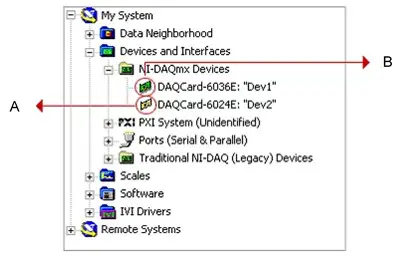
Figure 1 shows the Measurement & Automation Explorer (MAX) interface. Name the function of B.
MAX connection
Simulated device
Physical device
Software interface
Choose the best resolution for high accuracy for the data acquisition board.
6 bits
7 bits
8 bits
10 bits
Calculate the code width (resolution) for 12 bits DAQ device with a 0 to 10V input range and amplification is 0.5. (Give your answer in mV)
(a)
An Analog-to-Digital Converter (ADC) with a resolution of 10 bits is used to sample a signal with an input range of 0 to 5V. The sampling rate of the ADC is set to 1 kHz. Based on the sampling rate, determine the resolution and time interval between each sample
Resolution = 4.88 mV, Sampling Interval = 1 ms
Resolution = 2.44 mV, Sampling Interval = 0.5 ms
Resolution = 4.88 mV, Sampling Interval = 0.5 ms
Resolution = 2.44 mV, Sampling Interval = 1 ms
Explain the advantages of a digital signal in data acquisition systems.
i. Less susception to noise compared to analogue signals
ii. Easier to process and manipulate by microcontroller and computers
iii. Offer a wider range of values for representing data
iv. More complex to generate and interpret
i and ii
ii only
ii and iii
All above.
Explain how can a digital output signal from an Arduino be used to control an LED.
Connect the LED directly between a digital output pin and the ground
Connect the LED (anode) to a digital output pin through a current-limiting resistor and the cathode to the ground
Connect the LED (cathode) to a digital output pin through a current-limiting resistor, and the anode to ground.
Depends on the specific LED type and desired brightness.
Name a component that uses a count register to store the current count.
Capacitor.
Flip-flop
Relay
Timer
Identify the purpose of using a counter in a data acquisition system with Arduino
To convert analogue signals to digital values
To count and keep track of the number of events or pulses
To display sensor readings on an LCD screen
To store collected data on an SD card
Dray the block diagram of DAQ system which is consists of hardware and software

Demonstrate the steps involved in using a microcontroller to measure voltage using a voltage sensor for DAQ practical activities
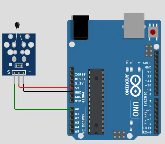
Figure show the temperature sensor connected to Arduino Board. Explain how a voltage level from a temperature sensor can be used as an analog signal in a DAQ system.
Explain the aliasing signal and suggest TWO (2) methods to prevent the aliasing signal effect.
Sketch a real-time graph of the temperature readings from the sensor over 30 minutes. Used the time interval of 5 minutes.

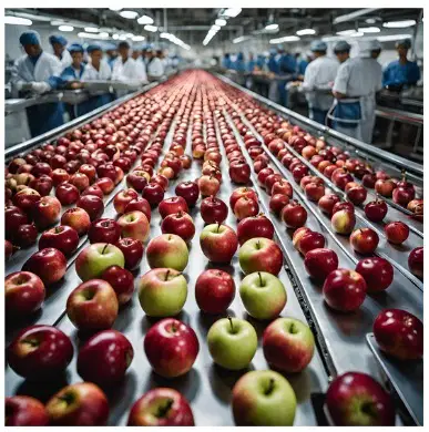
create the DAQ system question for students to count the apple on conveyor by using sensor and data logger.
**senaraikan jenis/ cara hardware, software, System Setup, Data Logging, analysis

