
 Worksheets
Understanding Schematic and Logic Diagrams
Total questions: 20
Worksheet time: 10mins
What is a schematic diagram?
A schematic diagram is a type of artistic representation of a landscape.
A schematic diagram is a complex mathematical equation used in engineering.
A schematic diagram is a detailed technical drawing of a building.
A schematic diagram is a simplified representation of a system's components and their interconnections.
What is the reference designation for Integrated Circuits?
U
Q
IC
X
What is the purpose of reference designation in schematics?
To indicate the voltage levels in the circuit.
To provide a visual representation of the circuit layout.
To uniquely identify components in schematics.
To show the flow of current through the components.
Explain the difference between logic symbols and electronic symbols.
Logic symbols are used to represent physical components in electronic circuits.
Logic symbols and electronic symbols are identical in meaning and usage.
Logic symbols are used in formal logic to represent abstract concepts, while electronic symbols represent physical components in electronic circuits.
Electronic symbols are used in formal logic to represent abstract concepts.
What standard is commonly used for electronic symbols?
ANSI Y32.2
ISO 9001
ANSI/IEEE 315
IEC 60617
What is the reference designation for transistors?
T
L
Q
U
What does the symbol 'GND' represent in a schematic?
Current
Voltage
Resistance
Ground

Identify the component.
N-MOSFET
JFET
P-MOSFET
PNP Transistor
What is the significance of using standardized symbols in schematics?
Standardized symbols are only necessary for electrical schematics.
Standardized symbols complicate the design process.
Standardized symbols improve clarity and communication in schematics.
Standardized symbols are used to increase the cost of production.
How can schematic diagrams aid in troubleshooting electronic circuits?
They provide a detailed explanation of circuit theory.
They eliminate the need for physical components in testing.
They automatically detect and fix circuit faults.
Schematic diagrams aid in troubleshooting by providing a clear visual representation of circuit connections and components, facilitating fault identification and systematic checking.
What is the direction of signal flow on a schematic diagram?
From right to left
From bottom to up
From up to bottom
From left to right

Identify the component
Potentiometer
Fuse
Switch
Transistor
___________ are a type of schematic that show the logical sequence of events in an electronic system.
Logic diagrams
Schematic diagrams
Wiring Diagrams
Block Diagrams

Identify the component.
Potentiometer
Light Emitting Diode
Light Dependent Resistor
Photodiode

Identify the component.
NOT gate
Operational Amplifier
Inverter gate
Tri-state buffer
Which one is an example of Integrated Circuits ( IC ) ?
Select all that apply.
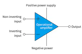

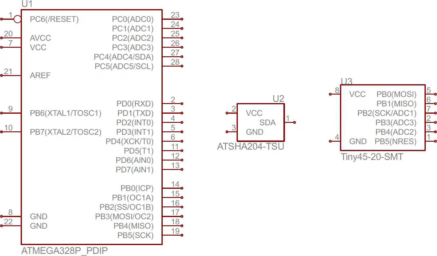
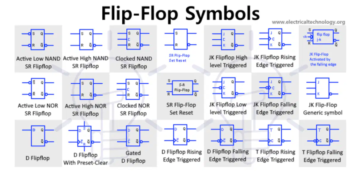
When designing a schematic diagram, the ________ are often established first.
Passive components
Active components
Bias resistors
Power source
In a complex schematic diagram, when assigning labels to each component, the number sequence flows ____________.
from left to right, bottom to top
from left to right, top to bottom
from right to left, top to bottom
from right to left, bottom to top
Which one is the best practice to place label and values of a component in a schematic diagram?
The reference designator and value numbers are placed above of vertical components and at the right side of horizontal components.
The reference designator and value numbers are placed above of horizontal components and at the left side of horizontal components.
The reference designator and value numbers are placed below of vertical components and at the right side of horizontal components.
The reference designator and value numbers are placed above of horizontal components and at the right side of vertical components.

Identify the logic symbol.
OR gate
XNOR gate
NOR gate
XOR gate

