
 Worksheets
Power-Consuming and Power-Passing Devices Quiz
Total questions: 30
Worksheet time: 15mins
What is the primary function of a power-passing device in an electrical system?
To use power to produce light or heat
To store electrical energy
To pass power without consuming it
To convert electrical energy to mechanical energy
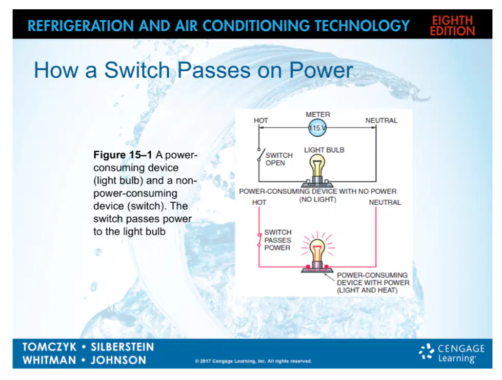
Based on the diagram, what happens when the switch is closed in the circuit?
The light bulb does not receive power
The switch consumes power
The light bulb receives power and lights up
The circuit is broken
What is the first step when troubleshooting a simple circuit with a voltmeter?
Verify the main power supply from the hot line to the neutral line.
Check the thermostat for voltage.
Replace the fuse immediately.
Turn off the main power supply.
What voltage reading would you expect across a properly functioning closed switch in a simple circuit?
0 volts
115 volts
230 volts
12 volts
When troubleshooting complex circuits, what should you check for specific voltage readings?
Thermostat, fan circuit, and cooling circuit
Only the main power supply
Only the light bulb
Only the compressor
If the indoor fan motor operates continuously, what is the likely position of the fan switch?
ON position
AUTO position
OFF position
RESET position
When will the indoor fan motor operate only when the compressor is running?
When the fan switch is in the "AUTO" position
When the fan switch is in the "ON" position
When the thermostat is off
When the fuse is blown
Why is it important to check the voltage at each point in a simple circuit when troubleshooting?
To identify where power is present or absent and locate faults
To increase the voltage in the circuit
To ensure the circuit is overloaded
To bypass the fuse
When troubleshooting a thermostat, what should you do first to ensure control voltage is present?
Check the cooling circuit
Turn the fan switch to the "ON" position
Replace the thermostat
Check the primary transformer only
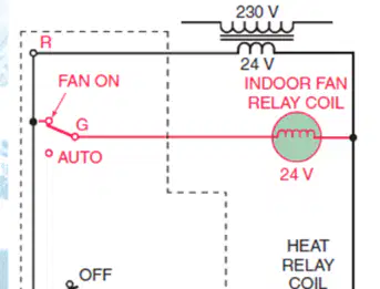
What is the purpose of adding a fan relay to the thermostat?
To allow the owner to switch the fan for continuous operation
To increase the voltage to the thermostat
To control the outdoor unit
To bypass the heating cycle
Why must the fan be operating during the heating cycle when a fan relay is added to the thermostat?
To prevent overheating of the relay coil
To ensure proper air circulation during heating
To reduce the voltage in the circuit
To activate the cooling circuit
If the circuits operate with the jumper wires but not with the thermostat, what does this indicate?
The fan is defective.
The cooling circuit is open.
The thermostat is defective.
The heat anticipator is working.
Why is the cooling anticipator in the cooling circuit considered unique according to the note in the material?
It is the only component in parallel with the fan.
It is one of the few times two loads are connected in series.
It is always off during the cooling cycle.
It is used only for heating circuits.
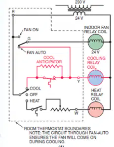
Select the correct description for the diagrams referenced in Figure 15–10 (A) and (B).
This is a placeholder for a diagram of a basic electrical circuit.
This is a placeholder for a diagram of a refrigeration compressor.
This is a placeholder for diagrams showing the cooling circuit with and without the cooling anticipator.
This is a placeholder for a diagram of a heat pump.
Which letters are common designations in a heat-cool thermostat subbase?
R, G, Y, and W
A, B, C, and D
X, Y, Z, and W
L, M, N, and O
What should happen if a jumper wire is placed between R and G in a thermostat subbase?
The indoor fan motor should start
The cooling cycle should start
The heating cycle should start
The system should shut down
If a relay's holding coil is rated at 24 volts, what voltage should be applied to it for proper operation?
24 volts
12 volts
48 volts
6 volts
If a component has the proper voltage supplied but fails to operate, what should be evaluated next?
The component itself
The power supply
The wiring insulation
The room temperature
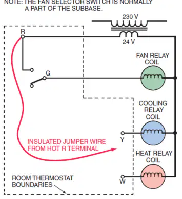
Select the correct diagram that shows the terminal designations and jumper wire placements in a heat-cool thermostat subbase, including the connections for R, G, Y, and W, and the associated relay coils.
Diagram of thermostat terminal designations and relay coil connections
Diagram of a water heater circuit
Diagram of a lighting system
Diagram of a solar panel setup
What does an infinite resistance reading on an ohmmeter indicate?
A closed circuit
A short circuit
An open circuit
A grounded circuit
Why should you never use an ohmmeter on an energized circuit?
It will give a false reading
It can damage the ohmmeter or cause injury
It will measure voltage instead of resistance
It will short the circuit
What does a measurable voltage reading across a switch indicate?
The switch is in the open position
The switch is in the closed position
The circuit is shorted
The power is off
What is the main difference between power passing and power consuming devices in wiring diagrams?
Power passing devices are shown on vertical lines, power consuming devices on horizontal lines
Power passing devices are always switches, power consuming devices are always loads
Power passing devices are not shown in diagrams
Power consuming devices are always colored red
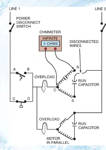
What does an ohmmeter reading of infinity across a motor run winding indicate?
The winding is open
The winding is shorted
The circuit is complete
The power is on
What must be present in order for the system to operate?
Control voltage
High resistance
Low temperature
Extra wiring
If the system does not operate, what should be checked at the transformer?
Voltage at the primary and secondary
Resistance at the load
Temperature of the wires
Color of the wires
Which instrument is used to measure control circuit amperage?
Ammeter
Voltmeter
Ohmmeter
Thermometer
If a component is supplied with proper voltage but fails to operate, what should be done?
The component should be evaluated
The voltage should be increased
The wires should be replaced
The circuit should be ignored
What do switches in parallel provide?
Alternate control sequences
Increased resistance
Lower voltage
Higher current
What do pictorial diagrams show?
Component locations, color-coded wires, and all electrical connections
Only the voltage levels
Only the current flow
Only the resistance values

