
 Worksheets
Technical Drawing Dimensions Review
Total questions: 25
Worksheet time: 13mins

If a part measures 3/4 inch on a scaled drawing but its actual size is 2 inches, what dimension should be shown on the drawing?
0.75
1.00
2.00
3.00
Why is it important to show the actual size of an object on a technical drawing rather than the scaled size?
To make the drawing look bigger
To ensure accurate manufacturing of the part
To save space on the paper
To confuse the reader
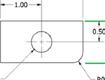
A student is dimensioning a rectangular block with a hole. They place the overall width, height, and depth dimensions farthest from the object, and the smaller, intermediate dimensions closer to the object. What principle are they applying?
Placing all dimensions randomly
Including overall dimensions in the three principal directions and nesting intermediate dimensions closer
Only dimensioning the largest features
Ignoring intermediate dimensions
What is the main purpose of including all dimensions in a technical drawing?
To make the drawing look more complex
To ensure the part can be produced or inspected correctly
To reduce the amount of information on the drawing
To confuse the manufacturer
According to the guidelines, what should you avoid when adding dimensions to a technical drawing?
Including unnecessary chain dimensions that add up to a given overall dimension.
Using only one method to show dimensions.
Adding as many dimensions as possible.
Ignoring overall dimensions.
What is the main guideline mentioned in the image for creating technical drawings?
Always use the largest possible dimensions
Do not include unnecessary dimensions
Add as many dimensions as possible
Only use metric units
Based on the diagram, which of the following best describes the correct way to dimension a technical drawing?
Include every possible measurement, even if not needed
Only include dimensions that are necessary for manufacturing or inspection
Use random numbers for dimensions
Add dimensions to every line in the drawing
According to proper dimensioning practices, how many views should a dimension be attached to?
Only one view
Two views
All available views
It does not matter
Based on the diagram, what is the main error shown in the dimensioning of the object?
A dimension is attached to more than one view using extension lines
The object is not fully dimensioned
The views are not aligned properly
The dimensions are written in the wrong units
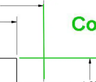
Given a technical drawing with three views, what is the best practice for attaching a dimension?
Attach each dimension to only one view
Attach each dimension to all views
Attach dimensions randomly
Do not use dimension lines

Given a technical drawing with multiple views, what is the best practice for dimension placement?
Place dimensions between adjacent views
Place all dimensions on a single view
Place dimensions outside the drawing border
Place dimensions only on the isometric view
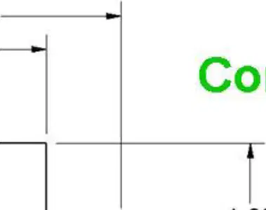
According to the guideline shown, what should you avoid when dimensioning a technical drawing?
Dimensioning to hidden lines
Dimensioning to visible lines
Using only metric units
Adding too many dimensions
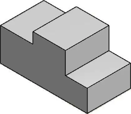
What does the diagram illustrate about dimension placement in technical drawings?
Dimensions should not be placed on the object unless necessary
All dimensions must be placed on the object
Dimensions are not needed in technical drawings
Only vertical dimensions should be placed on the object
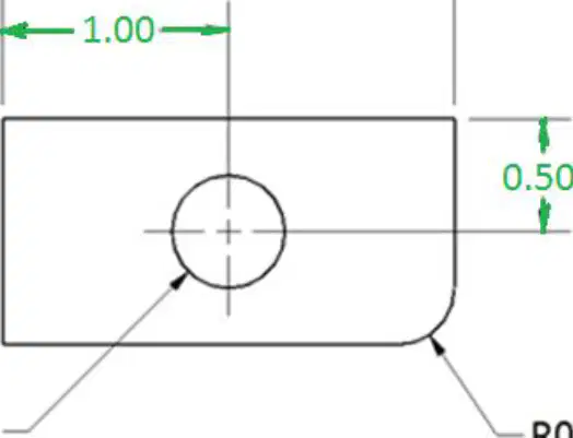
Why is it important not to cross dimension lines with other dimension or extension lines in technical drawings?
It helps keep the drawing clear and easy to read
It makes the drawing look more colorful
It allows for more dimensions to be added
It reduces the number of lines needed
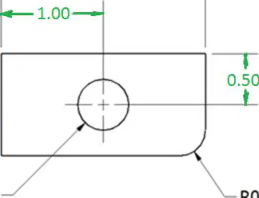
Given a technical drawing, how would you check if the dimensioning follows the correct practice described in the image?
Ensure that no dimension line crosses another dimension or extension line
Check if all lines are the same length
Make sure all dimensions are written in red ink
Verify that all lines are parallel
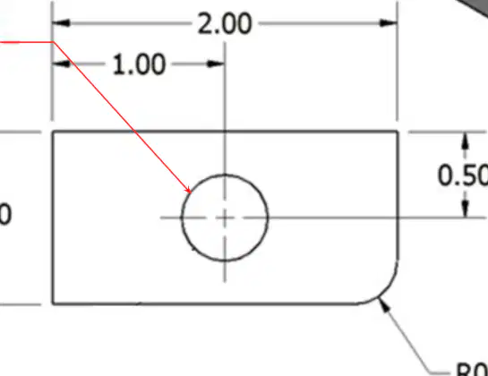
Why is it considered incorrect to cross dimension or extension lines with leader lines in technical drawings?
It can cause confusion and reduce the clarity of the drawing.
It makes the drawing look more detailed.
It is required for all engineering drawings.
It helps to highlight important dimensions.
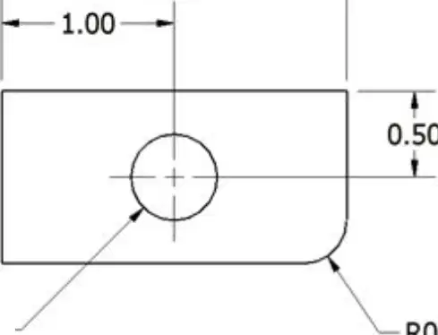
According to the guideline shown, what should you avoid when drawing leader lines in technical drawings?
Crossing dimension or extension lines with leader lines
Placing dimensions outside the drawing
Using only straight lines for all features
Adding unnecessary details to the drawing
If a leader line must be added to a technical drawing, what is the best practice regarding its placement?
Place it so it does not cross dimension or extension lines
Place it wherever there is space
Place it parallel to the longest edge
Place it at the center of the drawing
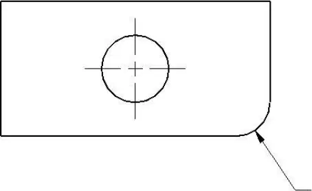
According to standard drafting practices, in which view should holes be located and sized?
In the view that shows the feature as a circle.
In the view that shows the feature as a rectangle.
In any view, as long as the dimensions are clear.
In the isometric view only.
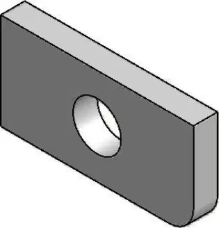
Given a technical drawing with a hole, what is the best practice for dimensioning the hole?
Dimension the hole in the view where it appears as a circle.
Dimension the hole in the side view only.
Dimension the hole in the isometric view.
Dimension the hole in all views.
In technical drawing, what is the purpose of dimensions?
To add colour to the drawing
To provide measurements and sizes of objects
To create a 3D effect
To make the drawing more artistic
Which of the following is a correct practice when placing dimension lines in a technical drawing?
Draw dimension lines through the object
Use different colors for each dimension line
Keep dimension lines spaced evenly and avoid crossing other lines
Place all dimension lines on top of each other
What is the recommended way to indicate the radius of a rounded feature in a technical drawing?
Write the word 'radius' after the number
Use the letter 'R' before the dimension value
Draw a square around the dimension
Underline the dimension value

