
 Worksheets
Air Separator
Total questions: 73
Worksheet time: 37mins
An air separator allows close proximity when positioning the cold feed and vent pipe in a central heating system. Which design feature of the air separator enables this?
It is an oversized pipe that creates a swirling flow to separate air
It is a narrow pipe that accelerates water to push air downstream
It is a flexible hose that lets the vent and feed be tied together
It is a perforated tube that traps air in its holes
When fitting an air separator, what is the intended effect on the cold feed and vent pipe relationship?
It permits close-coupled positioning without air issues
It requires the vent to be relocated far from the feed
It prevents the need for a vent by sealing the system
It isolates the cold feed from the boiler entirely
Select the best description of how an air separator functions inside the pipework.
Water enters an oversized body, swirls, and air is separated out
Water is compressed in a small chamber, dissolving the air
Air is injected into the stream to improve circulation
A mesh filter physically blocks water while air passes through
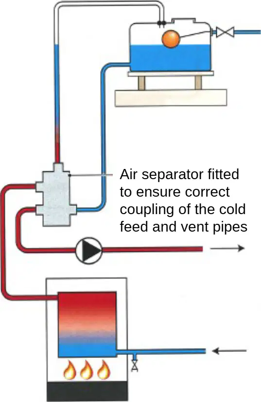
A system has humming noises and signs of internal rust. Based on good practice, which installation step would most directly address both issues?
Ensuring correct layout and air removal using an air separator
Increasing pump speed to force air to radiators
Reducing pipe diameter near the boiler to raise velocity
Adding extra bends to slow water and trap air
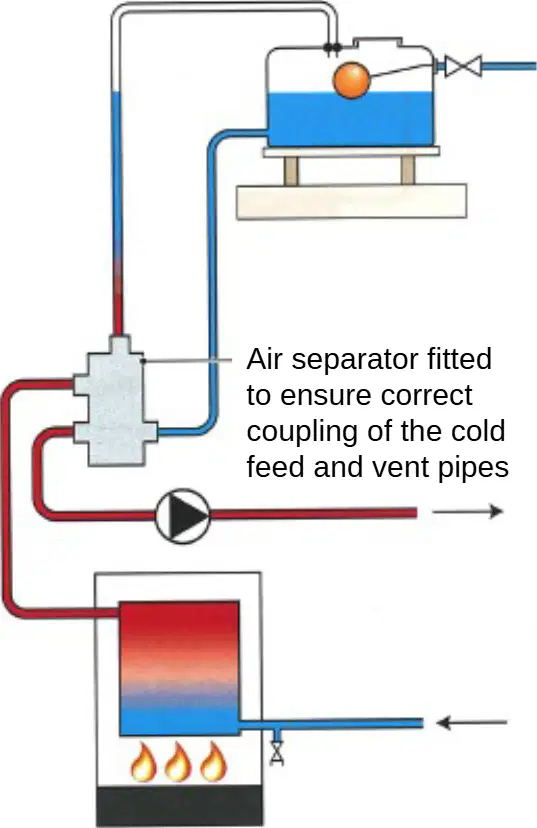
In the schematic of a central heating circuit with a boiler, pump, and expansion/vent, where should the air separator be fitted to ensure proper coupling?
At the junction where the cold feed and vent pipes meet the main circuit
At the boiler outlet only, downstream of all branches
Directly before the pump inlet on the return only
On the radiator tail farthest from the boiler
Which outcome is most closely linked to removing air from the system using an air separator?
Reduced noise and lower risk of corrosion
Increased system pressure and higher pump load
Elimination of the need for expansion control
Higher boiler flame temperature at all times
You are asked to specify pipework for a new open-vented system. To support quiet operation and longevity, which paired recommendation aligns with best practice from the material?
Install an air separator and arrange pipework correctly to remove air
Use only plastic pipe and omit any vent pipe for simplicity
Oversize the pump and remove the cold feed connection
Locate the cold feed and vent at opposite ends of the circuit
Why does the air separator’s oversized body matter for performance in a heating system?
It promotes a swirling motion that separates entrained air from water
It increases static pressure to dissolve gases into the water
It reduces flow so sediment can settle and block air movement
It cools the water so gases condense back into liquid
Based on the description, what is the primary purpose of using pump flanges with rubber or fibre washers when installing a circulator?
To provide an electrical earth to the pump body
To maintain a watertight seal at the connections
To reduce pump vibration transmitted to joists
To align the motor shaft with the impeller
When servicing a heating system circulator, which component allows the pump to be removed without draining the entire system?
Automatic air vent located at the boiler
Full bore valves positioned on either side of the flanges
Check valve on the return line
Expansion vessel service valve
A home has radiators that stay cool and domestic hot water that is only lukewarm. According to the guidance, which circulator condition is the most likely cause?
Pump running in reverse due to miswired polarity
Pump seized because of mineral scale
Pump operating sluggishly or performing poorly
Pump oversized for the pipework causing noise
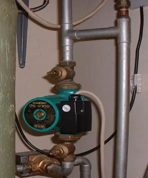
Look at the image of the red circulator installation. Which maintenance step should be performed first before unbolting the pump from the flanges?
Bleed all upstairs radiators to relieve pressure
Close the full bore isolation valves on both sides of the pump
Turn the speed selector to the lowest setting
Remove the rubber or fibre washers to release the seal
On either side of the circulator, integral to the flanges, are isolation valves. What is their main maintenance benefit?
They allow the pump to be electrically isolated without a fuse.
They allow easy removal or service of the pump without draining the system.
They automatically balance flow across all radiators.
They increase pump head by creating backpressure.
Which pairing correctly matches the circulator connection element to its function?
Pump flanges — provide an air vent point during filling
Rubber or fibre washers — create the watertight seal at the flanges
Isolation valves — secure the pump motor to the mounting bracket
Full bore valves — throttle flow to balance the system
When positioning a circulator in a heating system, why must it draw on the cold feed?
To promote positive pressure and reduce the risk of air being drawn into the system
To ensure the pump stays below its maximum temperature rating
To keep the return water temperature high for condensing efficiency
To prevent scale build-up on the impeller
What system condition is the correct target when siting the circulator to avoid air ingress and corrosion?
Neutral pressure at the pump inlet
Negative pressure at high points
Positive pressure throughout the circuit
Alternating pressure pulses near radiators
A technician installs a circulator but places it so it draws from the hot flow rather than the cold feed. Which problem is this most likely to cause, according to the guidance?
Reduced electrical efficiency only, with no hydraulic effects
Air being drawn into the system leading to corrosion issues
Immediate failure of the pump bearings due to overheating
Inability to close the full bore valves on maintenance
A circulator has multiple speed settings. What is the key reason to set these correctly during commissioning?
To allow the system to heat efficiently without generating system noise
To keep the pump running continuously at maximum speed
To ensure the rubber washers do not compress
To bypass the isolation valves during operation
During replacement of a circulator, the old washers are damaged. Which material options are specified as appropriate for new washers at the pump flanges?
Copper or steel
Nitrile or PTFE
Rubber or fibre
Silicone or cork
Which sequence best applies when removing a circulator for service, using only the features described?
Shut the boiler off, close the isolation valves on both sides of the pump, then unbolt at the flanges
Open all radiator valves, increase pump speed, then crack the flange bolts
Close the expansion vessel valve, remove the washers, then loosen the motor housing
Purge air at the highest vent first, then open the full bore valves and remove the pump
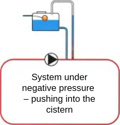
Refer to the left-hand diagram. The pump is placed so the cistern connection is on the discharge side of the circulator. What system condition does this create?
Positive pressure with vent protection
Negative pressure pushing into the cistern
Neutral pressure at the cold feed
Balanced pressure across the pump
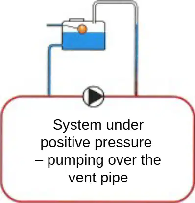
In the centre diagram, the pump discharges toward the open vent. What is the immediate effect shown?
Pumping over the vent pipe (positive pressure)
Drawing air into the return (negative pressure)
No movement at the vent (neutral zone)
Reverse flow through the boiler
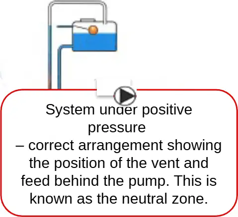
According to the right-hand diagram, where should the vent and cold feed be positioned relative to the circulator to create the neutral zone?
On the discharge side of the pump, close to the boiler
Behind the pump on its suction side
At the highest point of the vent pipe only
Anywhere on the return as long as pipe sizes are equal
Why is the circulator’s position important in relation to the cold feed and vent?
To match pipe material specifications
To achieve the positive pressure required by the system
To reduce boiler firing rate
To eliminate the need for an expansion cistern
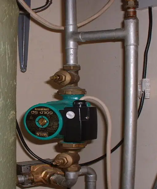
The material states that, instead of an air separator, which layout is commonly used?
T-frame configuration
L-loop configuration
H frame configuration
Parallel twin-pump configuration
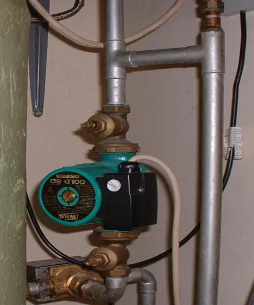
Where must the vent and cold feed be installed relative to the circulator in an H frame layout to ensure correct operation?
On the discharge side of the circulator
On the suction side of the circulator
At the boiler return after the pump
Directly above the pump outlet only
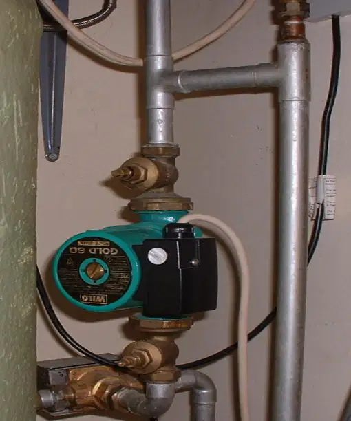
What maximum distance should separate the vent and the cold feed connections in the H frame arrangement?
50 mm
100 mm
150 mm
300 mm
In the H frame setup, why keep the vent and cold feed close together?
To ensure the circulator always draws on the cold feed
To increase head loss through the pump
To keep the vent pipe cooler
To balance the boiler return temperature

On the schematic, the neutral point is labelled at the base of which connection?
The open vent near the cistern outlet
The cold feed connection
The boiler flow outlet
The pump discharge to the system
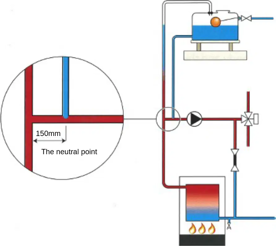
According to the schematic, how does the correct pipework layout establish a neutral zone?
By placing the pump above the cistern waterline
By positioning the pump between two non-return valves
By connecting the vent and cold feed closely at the suction side so pressure at the base of the cold feed remains unaffected by pump head
By increasing pipe diameters on the boiler return only

Which change would most likely cause pumping over at the open vent based on these diagrams?
Moving the vent connection to the pump suction close to the cold feed
Moving the pump so it discharges directly toward the vent connection
Reducing the distance between vent and cold feed to 150 mm
Lowering the cistern water level slightly
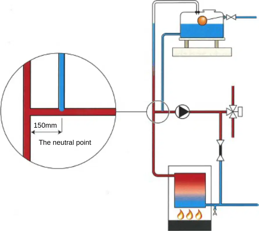
When setting out an H frame, which statement best applies to the cold feed connection?
It should be on the pump discharge to add pump head to the cistern.
It should be at the neutral point so the pump neither adds nor subtracts pressure there.
It should be two metres from the vent to avoid turbulence.
It should be at the top of the vent to trap air.
A magnetic system cleaner is installed on a heating system. What is its main function during normal operation?
To chemically neutralize limescale in the water
To collect corroded iron particles (magnetite) using a magnet
To increase pump pressure to move water faster
To filter out all dissolved minerals from the water
During scheduled servicing of a heating system fitted with a magnetic system cleaner, which action helps maintain good system water quality?
Remove the magnet to flush away accumulated magnetite
Add extra antifreeze to raise water viscosity
Backwash the radiator fins to remove dust
Open all radiator bleed valves to vent air for 24 hours
Different styles and makes of magnetic system cleaners exist. Which shared design feature enables them to remove magnetite?
A ceramic screen that traps all rust flakes
A permanent magnet that attracts corroded iron particles
A UV lamp that sterilizes microorganisms
A reverse-osmosis membrane that filters dissolved salts
A system shows recurring black sludge even after installing a magnetic system cleaner. Based on how these devices work, which check best applies the concept to troubleshoot the issue?
Verify the magnet is present and positioned so flow passes it for collection
Reduce system temperature so salts crystallize and settle out
Replace copper pipes with plastic to stop limescale formation
Increase water pH to dissolve iron particles into the water
Which statement best explains the primary function of an inhibitor in a central heating system?
It chemically protects the system against scale and corrosion.
It increases water hardness to prevent sludge formation.
It mechanically filters debris from the primary circuit.
It raises boiler temperature to improve heat transfer.
A heating system requires an inhibitor top-up. According to best practice described, which method is acceptable for adding inhibitor?
Introduce it via the feed and expansion (F&E) cistern or dose through a radiator.
Inject it into the gas supply upstream of the burner.
Blend it with engine coolant and circulate through the pump.
Spray it onto external pipework lagging to absorb through joints.
Manufacturers claim inhibitors contribute to system efficiency. Which outcome aligns with these claims when inhibitor levels are maintained?
Extended system life with maximum efficiency and minimum fuel usage.
Shortened boiler lifespan due to chemical wear and higher fuel usage.
No change in lifespan but increased water consumption.
Improved aesthetics of pipework paint without efficiency impact.
Where must the primary vent terminate in an open-vented system treated with inhibitor, and why?
Over the F&E cistern because the primaries contain chemical inhibitor.
Into the flue because combustion gases neutralize chemicals.
Below the boiler return to avoid entraining air into the circuit.
To a drain to discharge any treated water safely away from the system.
A domestic radiator has a valve at each end. Which option correctly matches the valve type to its primary user and purpose?
Wheel head valve — used by the engineer to isolate radiators for maintenance
Wheel head valve — used by the customer to adjust water flow to suit heating needs
Lock-shield valve — used by the customer to turn the radiator fully on and off
Lock-shield valve — used by the installer to add thermostatic control for each room
Two identical valves are fitted to a radiator, but one has its wheel head removed and capped. What is the functional reason for fitting this lock-shield valve?
It prevents air from entering the radiator during filling
It gives the engineer controlled access for system balancing
It allows the customer to fine-tune room temperature daily
It automatically shuts off flow if the pump stops
When setting up a heating system, which action best applies the concept of radiator balancing using the correct valve?
Adjust the wheel head valve at each radiator until the room feels comfortable to occupants
Fully open both valves so that all radiators heat at the same rate without adjustment
Partially close the lock-shield valve to regulate flow rates so all radiators heat evenly
Replace the wheel head valve with a thermostatic head to maintain constant flow
According to regulations, what requirement applies to thermostatic radiator valves (TRVs) on heating systems?
TRVs are optional on new systems only
Building Regulations part L and the Heating Compliance Guide require TRVs to be fitted on systems
TRVs are only required in commercial buildings
TRVs must be installed only on return pipes
A TRV replaces which component to allow control of a single radiator’s temperature?
Lockshield valve
Wheel head valve
Room thermostat
Bypass valve
What does the special head on a TRV respond to for controlling the valve?
Water flow rate through the radiator
Ambient air temperature in the room
Boiler return temperature
Sunlight intensity at the window
Inside the TRV head, the sensor contains a volatile liquid. What happens when the room warms up?
The liquid expands, pushing a pin down to close the valve
The liquid solidifies and locks the valve open
The liquid evaporates and opens the valve wider
The liquid contracts, pulling the pin up to open the valve
A room begins to cool after heating is turned down. How does the TRV respond to allow the radiator to heat up again?
The volatile liquid contracts, opening the valve
The volatile liquid expands further, closing the valve tighter
The valve locks at its previous position
The TRV switches to manual bypass mode
When installing TRVs in a system, what must be true about at least one radiator and why?
All radiators must have TRVs to balance the system
One radiator must be left without a TRV, preferably in the same room as the room thermostat
Two radiators must be left without TRVs to prevent overheating
Only bathroom radiators should lack TRVs to aid ventilation
A radiator with a TRV is temporarily removed for decorating. What should be fitted to the valve head during this period?
A lockshield cap to seal the return
A decorator’s cap over the head to the valve
An air vent plug to prevent air entry
A remote sensor phial to maintain control
Long curtains obstruct a radiator where a TRV is needed. What installation choice best maintains proper temperature sensing?
Install the TRV behind the curtains without changes
Use a remote head so sensing is away from obstructions
Fit the TRV on the return to reduce heat
Disable the room thermostat and rely on the TRV only
Older practice placed TRVs only on the flow pipe. What is true of modern TRVs and what caution applies?
They are reversible, but incorrect flow direction may cause valve seat rattle and vibration
They must still be installed on the flow only to avoid water hammer
They are non-reversible and must be installed on the return
They are reversible and have no issues with flow direction
Refer to the image of two TRV bodies with numbered heads. Which scenario could make a radiator noisy after installation?
Fitting a decorator’s cap during painting
Installing a reversible TRV with water flowing the wrong way through the valve body
Leaving one radiator without a TRV in the thermostat’s room
Setting the dial to a lower number
TRVs can include remote sensors. In what situation are these particularly useful?
When the boiler is in a separate building
When long curtains or furniture could interfere with the phial’s operation
When the system lacks a room thermostat
When the radiator is mounted below floor level
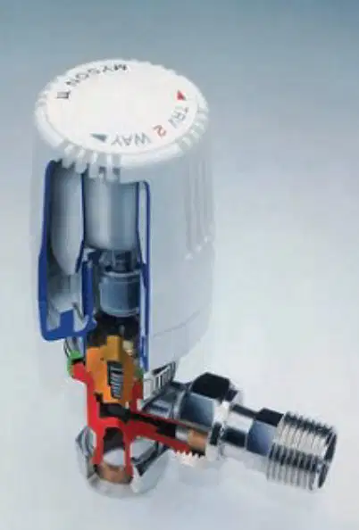
Considering the cutaway diagram of a TRV showing internal components and a capillary-linked remote sensor, what is the role of the phial in TRV operation?
It stores water to dampen flow fluctuations
It houses the volatile liquid that reacts to ambient temperature for valve actuation
It filters debris from the heating circuit
It measures boiler pressure via the capillary tube
Which situation best explains why an Automatic Bypass Valve (ABV) is necessary in a heating system with thermostatic radiator valves (TRVs)?
TRVs open fully and reduce system resistance, causing pump cavitation.
TRVs close while the circulator is still running, causing a rise in system pressure.
The boiler shuts down and cools the water, decreasing static pressure.
Air vents close, preventing water from circulating through radiators.
What is the primary function of an ABV in relation to system pressure and pump life?
It isolates the pump from the system to stop flow completely.
It releases built-up pressure through the system pipework, reducing strain on the pump and prolonging its life.
It increases discharge pressure to improve radiator heating speed.
It vents air from the pump housing to prevent air locking.
When TRVs close but the circulator continues to operate, what role does the ABV play in system operation?
It diverts some flow to maintain circulation and prevent excessive pressure rise.
It turns off the circulator automatically to stop over-pressurisation.
It opens the boiler gas valve to increase heat output.
It drains water from the system to reduce volume.
Where is an ABV typically installed within a hydronic heating system?
On the cold water mains before the filling loop
Between the primary flow and return pipes
Directly on each radiator body
Inside the flue to control exhaust pressure
Some boilers include an ABV from the factory. What condition does this built‑in ABV specifically accommodate?
It allows the flow of water through the boiler if the TRVs and zone valves close.
It guarantees constant domestic hot water temperature regardless of demand.
It prevents limescale formation by dosing inhibitor automatically.
It ensures radiators heat even when the boiler is off.
A system has frequent pump failures after occupants fit TRVs to most radiators. Which adjustment would most directly address the underlying cause based on ABV principles?
Increase pump speed to force water through closed TRVs.
Install or correctly set an ABV to provide a bypass path when TRVs close.
Fit larger radiators to lower return temperatures.
Replace the boiler with a higher output model.
Select the best description of how an ABV contributes to safe boiler operation when all heating circuits are shut by controls.
It holds all water stationary so the boiler cools more slowly.
It maintains a controlled flow path through the boiler to prevent dead‑heading and pressure spikes.
It bleeds trapped air out of the heat exchanger automatically.
It bypasses the boiler entirely so no water enters the heat exchanger.
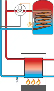
Consider the schematic showing primary flow and return with an ABV (assume a typical installation). If all TRVs are closed, what flow path exists due to the ABV?
No flow is possible; the pump stalls until TRVs reopen.
Flow circulates from primary return to cold mains via the filling loop.
Controlled flow bypasses from the primary flow to the primary return through the ABV.
Flow is redirected to domestic hot water only, avoiding the boiler.
A filling loop is described as a flexible, temporary connection used in heating installations. In which context is it correctly applied?
Linking incoming mains to a pressurised sealed central heating system for topping up pressure
Permanently connecting a cold-water storage cistern to the hot-water cylinder
Providing a constant bypass between the flow and return on an open-vented system
Connecting rainwater harvesting storage to the domestic hot water outlet
After repressurising a sealed system using a filling loop, what action is required by Water Regulations?
Leave the loop in place with both isolators open for quick refilling
Disconnect the filling loop after use to prevent backflow routes
Secure the loop with a secondary clamp but keep it connected
Close only the mains-side isolator and leave the loop fitted
What valve arrangement protects the incoming mains associated with a filling loop, as required by Water Regulations?
Single non-return valve fitted on the heating side only
Double check valve on the incoming mains to prevent backflow
Pressure relief valve installed between the boiler and loop
Thermostatic mixing valve on the mains inlet
On either side of a filling loop used with combination boilers, which control component is fitted and how is it operated?
Gate valve operated with multiple turns for throttling
Ball-type quarter-turn isolator for open/close control
Pressure reducing valve adjusted with a screw cap
Stopcock requiring more than one full turn to close
A sealed heating system begins to overpressurise due to a component fault. Which action of the pressure relief valve (PRV) protects the system?
It shuts the system pump to stop circulation
It opens to discharge excess pressure safely at a factory-set pressure
It diverts flow back to the boiler to increase temperature
It isolates the expansion vessel to restore its charge
A technician finds frequent PRV discharges on a sealed system. Based on common causes, which fault should be investigated first?
Blocked cold water inlet filter causing low supply pressure
Expansion vessel failure or loss of charge leading to pressure build-up
Undersized discharge pipe causing slow drainage
Thermostat stuck open causing constant circulation
When selecting a replacement PRV for a sealed system, which specification must match the original to ensure proper protection?
The pump flow rate rating
The factory-set discharge pressure
The pipe material of the distribution system
The thermostat calibration range
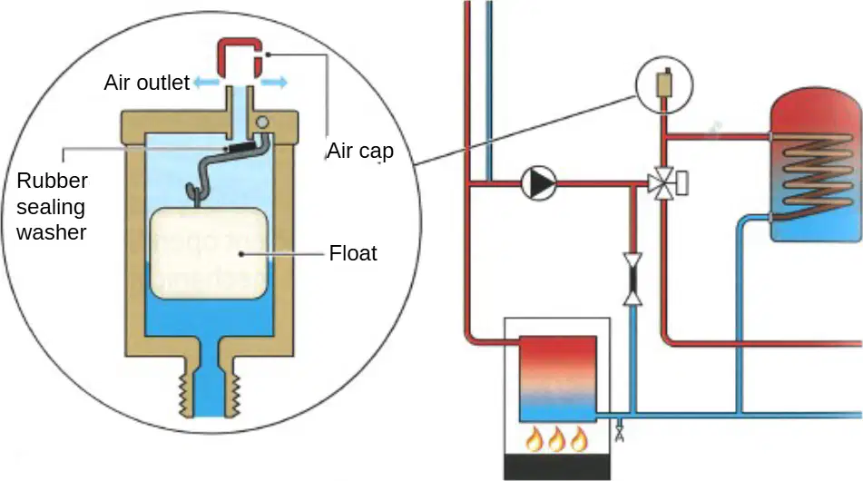
Refer to the diagram of the automatic air release valve. At what location in a plumbing/heating system should this component be installed to function correctly, and why? Choose the best option.
At high points where air accumulates so it can vent automatically
At the lowest drain point to flush sediment from the system
Midway along horizontal runs to balance water pressure
Adjacent to radiators to manually bleed trapped air
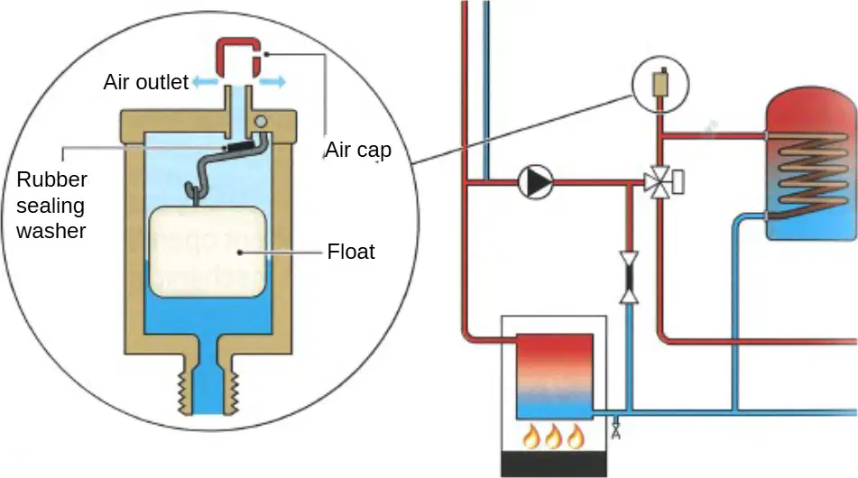
Using the cutaway view of the automatic air release valve, which internal part directly enables the valve to close automatically after air has been expelled?
The float that rises with water and seals the air outlet
The air cap that is screwed down by hand to stop the flow
The rubber sealing washer that dissolves air bubbles chemically
The pump in the system that reverses flow to shut the port
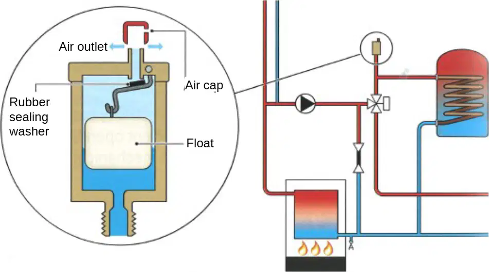
A boiler has intermittent gurgling due to trapped air. Based on the diagram, which component would automatically vent this air without manual intervention?
Automatic air release valve installed inside the boiler
Pressure relief valve connected to the expansion vessel
Manual bleed screw on a radiator
Non-return valve on the pump discharge