
 Worksheets
Cold water mock exam
Total questions: 73
Worksheet time: 37mins
State which regulation set legal requirements for the design, installation, operation and maintenance of plumbing systems, water fittings and water-using appliances, with the specific purpose to prevent misuse, waste, undue consumption or erroneous measurement of water and, most importantly, to prevent contamination of drinking water.
Water Supply (Water Fittings) Regulations 1999
Building Regulations Part G: Sanitation, hot water safety and water efficiency
BS 8558: Guide to the design, installation, testing and maintenance of services supplying water for domestic use
WRAS Materials Guidance 2019
Identify which British standard is the Specification for installations inside buildings conveying water for human consumption.
12056
1010
8000
BS EN 806
Identify which British standard is the Guide to the design, installation, testing and maintenance of services supplying water for domestic use within buildings and their curtilages.
806
1212
6700
8558
State which organisation produces the water regulations and the water fittings and material directory.
Water Regulations Advisory Scheme (WRAS)
Chartered Institute of Plumbing and Heating Engineering (CIPHE)
British Standards Institution (BSI)
Health and Safety Executive (HSE)
Identify what the abbreviation WRAS stands for.
Water requirement and standards
Water regulation advice scheme
Water regulation advisory scheme

Identify the type of well indicated by the arrow in the upper diagram.
Shallow well
Deep well
Artesian well
Land spring

Identify which of the above wells is not wholesome water.
Shallow well
Deep well
Artesian well
Confined aquifer well
Indicate on the pH scale which value represents neutral water.
6
7
8
9
Identify which chemical is in permanent hard water.
Calcium sulphate
Calcium bicarbonate
Sodium chloride
Potassium nitrate
Identify which chemical is in temporary hard water.
Calcium bicarbonate
Calcium sulphate
Magnesium chloride
Sodium carbonate
State the problem with temporary hard water when heated above 65 degrees.
Formation of scale due to precipitation of calcium carbonate
Corrosion of copper pipes due to acidic attack
Increase in water alkalinity causing taste issues
Reduction in dissolved oxygen leading to odor
Describe the easiest way to determine if you have hard or soft water.
Perform a soap lather test and observe ease of forming suds
Measure electrical conductivity with a meter
Evaluate water taste differences
Inspect water color in a clear glass

Identify the system shown: a water treatment plant feeds a network of water mains that supply houses and other buildings through branch services.
Municipal potable water distribution network
Rainwater harvesting and storage system
Sanitary sewer collection network
Fire sprinkler piping layout

Identify the fitting shown and state where it is used: a chain-mounted tool clamped to a live main with a crank and blue handle.
Under-pressure (hot) tapping machine used to make service connections to live water mains without shutting down supply
Gate valve used to isolate an individual fixture within a building
Handheld pipe cutter used to cut copper tube prior to soldering
Fire hydrant head used for emergency fire-fighting connections

Identify the systems shown inside the houses: fixtures feed to a grey water collection and filtration, pumped to an underground storage cistern and returned to a high-level grey water storage cistern for supply.
Domestic greywater recycling system with storage cistern and pump
Central heating (hydronic) loop with boiler and radiators
Ventilation ductwork with mechanical extract fans
Rainwater downpipe and roof drainage system
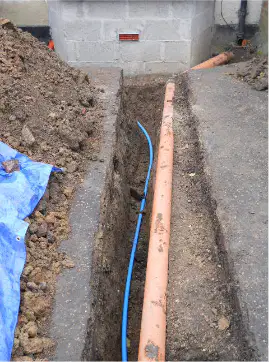
Identify the type of pipe shown in the trench and how you would confirm that it is carrying water.
Blue MDPE potable water service pipe; confirmed by blue color coding and water-specific markings on the pipe
Orange PVC electrical conduit; confirmed by cable pull strings and electrical hazard labeling
Black polyethylene gas main; confirmed by yellow stripe and gas service tags
Grey PVC soil pipe; confirmed by soil/waste labels and connection to sanitary fixtures
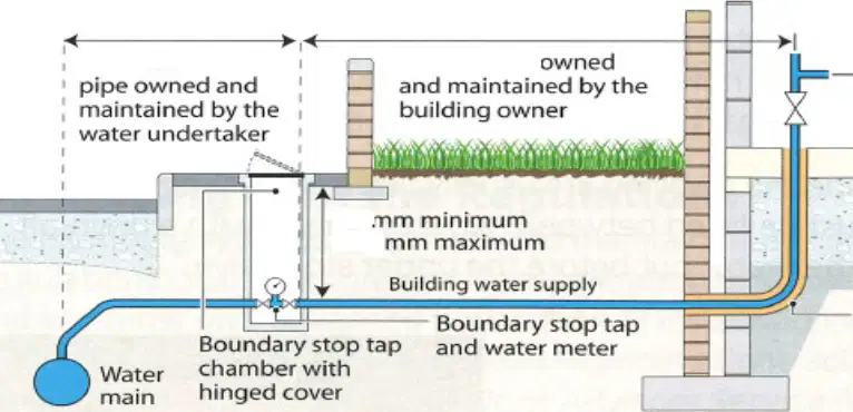
State the minimum and maximum depth for a buried water service pipe.
450 mm minimum, 900 mm maximum
600 mm minimum, 1200 mm maximum
750 mm minimum, 1350 mm maximum
900 mm minimum, 1500 mm maximum
Give the name of the pipe that runs from the water main to the boundary stop valve.
Communication pipe
Supply pipe
Service pipe
Distribution pipe
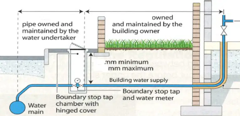
Give the name of the pipe that runs from the boundary stop valve to the domestic property.
Communication pipe
Supply pipe
Riser pipe
Branch pipe
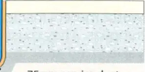
State the minimum distance that an uninsulated service pipe must be kept from the external wall where it enters the property.
25 mm
50 mm
75 mm
100 mm
Identify which type of copper tube can be used underground.
R220 soft copper
R250 half hard
R220 soft coil micro-bore
R290 hard
State the first two fittings that must be installed on the service pipe as it enters the property.
Internal stop valve and drain off valve
Pressure reducing valve and double check valve
Double check valve and water meter
Gate valve and strainer
State where the internal stop valve should be installed.
At the highest point of the system, near the loft tank
Close to the point of entry on the ground floor, readily accessible
Outside the property, beside the boundary box
Next to the boiler inside the plant room
State the two places where the water to the service/supply pipe can be isolated.
At the boundary stop tap and at the internal stop valve
At the water main and at the boiler drain cock
At the kitchen mixer tap and at the shower valve
At the pump isolator and at the PRV gauge
Identify three areas where a water meter may be located.
In a boundary box at the property edge or footpath
Inside near the point of entry by the internal stop valve
In the loft next to the cold water storage tank
In an external wall box or meter chamber
Behind the kitchen plinth under the sink
Identify the BS number that applies to stop valves for domestic water services.
BS 1212
BS 1254
BS 806
BS 1010
State which type a drain off valve must be.
Full-bore drain off valve
Screw-down drain off cock
Spring-loaded check valve
Lever ball non-return valve
State the most cost‑effective procedure to repair a stop valve when the valve jams.
Replace the entire valve body and pipework
Repack the gland and replace/renew the washer and jumper
Install a pressure reducing valve upstream
Fit a strainer to remove debris
Identify where a drain off valve should be installed apart from above the stop valve.
At the highest point of the system
At the lowest point of the installation
On every branch after each tap
Inside the boiler casing
When installing appliances, identify the two key tests that must be carried out.
Static pressure test
Flow rate (discharge) test
Electrical continuity test
Water hardness test
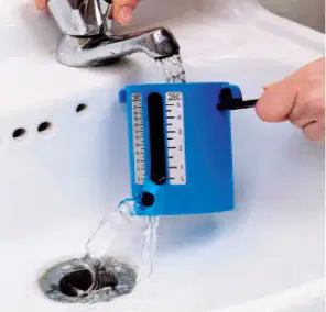
Identify the equipment shown: a small calibrated cup used to measure discharge at a tap.
Flow cup for measuring tap flow rate
Pressure gauge for measuring static pressure
Stop valve spanner
Non-return valve
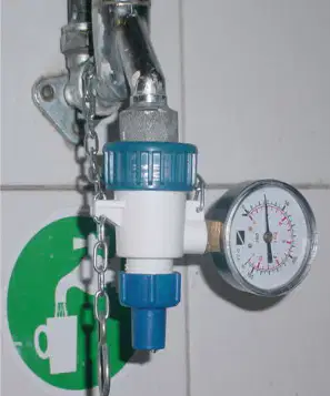
Identify the equipment shown: a gauge and regulator assembly fitted to a cold water line.
Pressure reducing valve with pressure gauge
Flow cup for measuring discharge
Double check valve
Gate valve with sight glass
Identify factors that may impact the accuracy of flow and pressure measurements.
Partially closed or faulty stop valves
Blocked tap aerators or strainers
Long small‑bore pipe runs and bends
Pressure reducing valve settings or upstream restrictions
Ambient temperature variation only
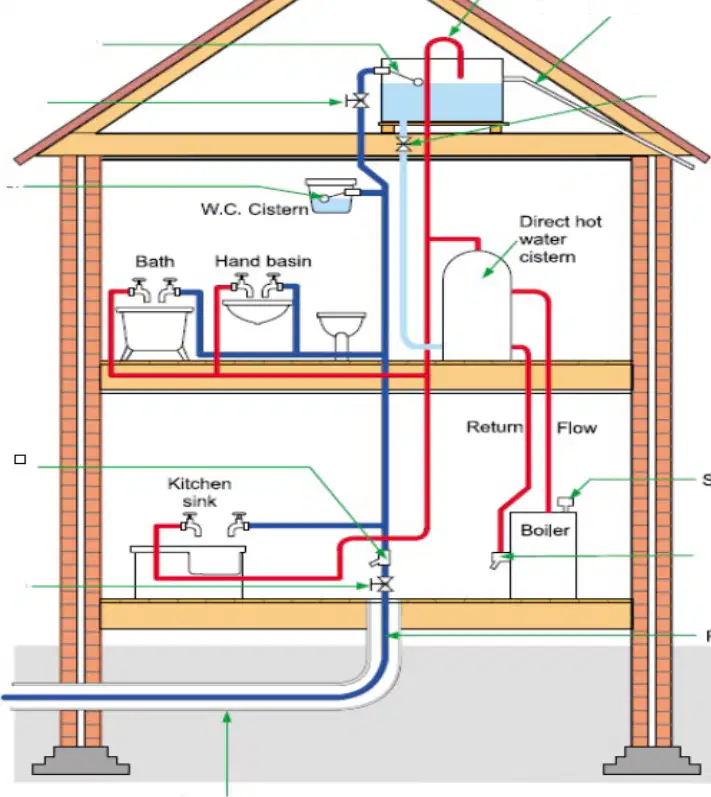
Using the house plumbing diagram showing a cold water storage cistern supplying bathrooms, a boiler with flow and return to a hot water cylinder, a rising main to the kitchen sink, and vent/safety pipework, select three advantages of the above system.
Provides stored water for continuity during mains interruptions
Reduces backflow risk to the mains by supplying most outlets from the cistern
Gives high mains pressure at all taps including bath and basin
Allows quieter operation because many outlets are not at mains pressure
Requires fewer components because no cistern is needed
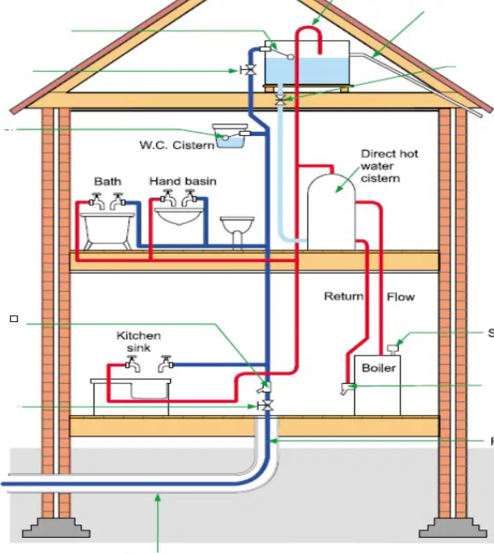
Using the same diagram, select three disadvantages of the above system.
Lower outlet pressures at cistern‑fed taps compared with mains
Takes more space for cistern and associated vent/pipework
Increased risk of stagnation or contamination if cistern hygiene is poor
Provides no reserve of water during a supply failure
Cannot be combined with a boiler and hot water cylinder
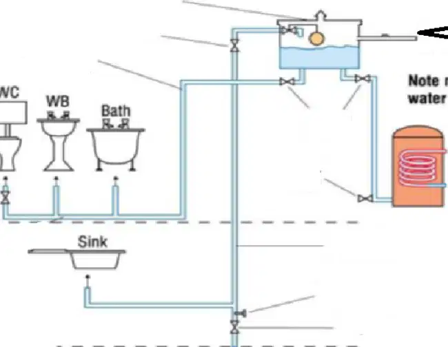
Using the plumbing layout showing a storage cistern feeding most fixtures (WC, wash basin, bath) and a vented hot water storage vessel, select three advantages of the above system.
Provides reserve water from the cistern during mains interruptions
Balances pressures between hot and cold supplies for bathroom fixtures
Quieter operation because many outlets are gravity‑fed
High mains pressure delivered to all fixtures, including bath and basin
Eliminates the need for a cistern and vent pipework
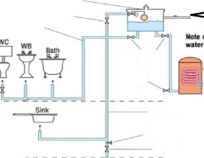
Using the same diagram, select three disadvantages of the above system.
Lower delivery pressures at cistern‑fed outlets
Requires additional space for cistern, supports, and pipework
Potential for stagnation or contamination if the cistern is not maintained
No stored water is available during supply failure
Hot and cold supplies cannot be balanced
Describe the easiest way to determine if the system is direct or indirect.
Observe whether most outlets (except the kitchen sink) are supplied from a storage cistern rather than directly from the mains; if so, it is an indirect system
Measure the temperature of water leaving the boiler
Count the number of fixtures connected to the system
Check whether the kitchen sink is supplied by a pump
Identify the reasons for using approved water fittings in cold water plumbing systems.
Prevent contamination and protect public health by ensuring materials are safe for potable water
Ensure compliance with water regulations and legal requirements
Improve aesthetic appearance of bathrooms
Reduce leakage and enhance reliability through tested performance
Increase water bills
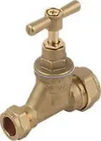
Identify the fitting shown: a brass stop valve with a T-handle installed inline. Where would you typically find it?
Main water supply stopcock at a property entry
Under-sink appliance isolation on a flexible hose
External hose connection backflow protection
Drain point at a hot-water cylinder or heating circuit
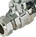
Identify the fitting shown: a chrome lever-operated ball valve with compression ends. Where would you typically find it?
Isolation valve on appliance or fixture supply pipework
Low-pressure gravity hot-water main control
Double check valve on outside tap supply
Pressure-reducing valve on incoming main
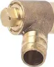
Identify the fitting shown: a small brass angled valve body with cap. Where would you typically find it?
Drain-off cock used to drain heating circuits or cylinders
Main stopcock on incoming cold main
Double check valve for hose bib
Automatic leak-detection shut-off valve
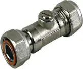
Identify the fitting shown: a small chrome inline valve with a screwdriver slot on the body. Where would you typically find it?
Service isolation valve under a basin, toilet, or appliance
Gate valve on low-pressure systems
Double check valve serving an outside tap
Automatic electric shut-off valve on main
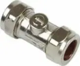
Identify the fitting shown: a chrome inline body with a central bulge. Where would you typically find it?
Double check valve on an external hose tap or appliance connection
Service isolation valve under a sink
Gate valve on gravity hot-water
Drain-off cock at the base of a cylinder
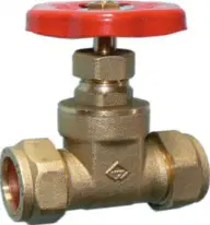
Identify the fitting shown: a brass gate valve with a red handwheel. Where would you typically find it?
On low-pressure gravity-fed hot-water or heating circuits
As a double check valve for hose outlets
As an automatic leak-detection shut-off device
As an under-sink service isolation valve
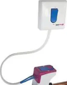
Identify the fitting shown: a white wall module with a wired actuator connected to an inline valve on copper pipe. Where would you typically find it?
Automatic leak-detection shut-off on the incoming main
Manual stopcock at property boundary
Outside hose bib backflow preventer
Drain-off cock for heating circuits
Which of the above fittings is used on low pressure systems?
Gate valve with red handwheel
Lever-operated ball valve
Service isolation valve (screwdriver slot)
Double check valve
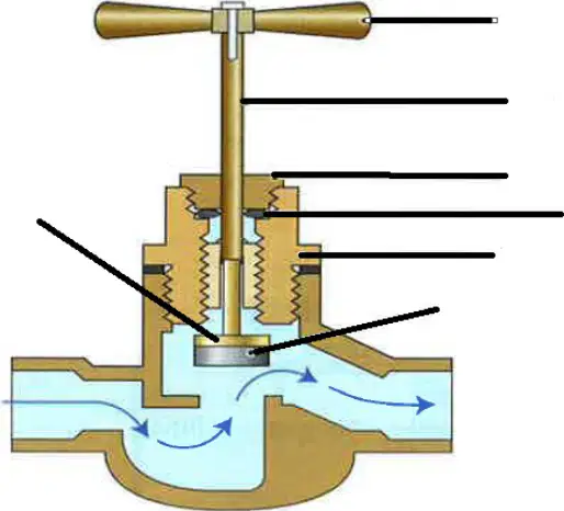
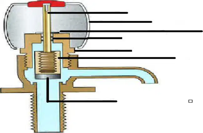
In the stop valve cross-section shown, which component seals against the seat to stop the flow?
Washer (jumper)
Olive
Compression nut
Spindle thread
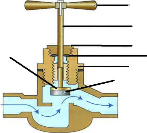
In the stop valve cross-section shown, what is the stationary surface the washer seals against?
Valve seat
Gland packing
Compression fitting
Handle
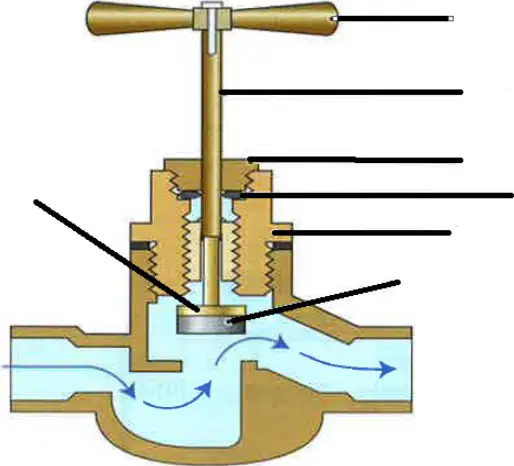
In the stop valve cross-section shown, which part the handle turns to raise and lower the washer?
Spindle
Olive
Body casting
Drain port
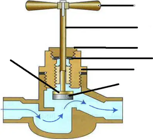
In the stop valve cross-section shown, which component prevents leakage around the spindle?
Gland packing
Washer (jumper)
Seat
Compression nut
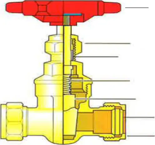
In the compression fitting diagram, what is the name of the soft metal ring compressed to make the seal?
Olive
Ferrule nut
Washer
Seat
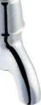
Identify the tap type shown: pair of individual chrome pillar taps for hot and cold at a basin.
Pillar taps
Bib taps
Outside hose bibcock
Single-lever mixer tap
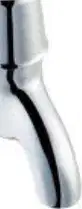
Identify the tap type shown: wall-mounted chrome taps with star handles, one marked blue and one red.
Bib taps
Pillar taps
Single-lever mixer tap
Outside hose bibcock
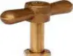
Identify the tap type shown: a brass outdoor tap with hose connector and T-handle.
Outside hose bibcock
Pillar taps
Single-lever mixer tap
Bib taps (indoor)
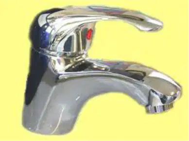
Identify the tap type shown: a single chrome body with one lever controlling mixed flow.
Single-lever mixer tap
Pillar taps
Bib taps
Outside hose bibcock
Label the following diagrams for the cold water storage cistern float-operated inlet valve. Which valve type is illustrated in both diagrams?
Float-operated (ballcock) valve
Gate valve
Non-return (check) valve
Pressure-reducing valve
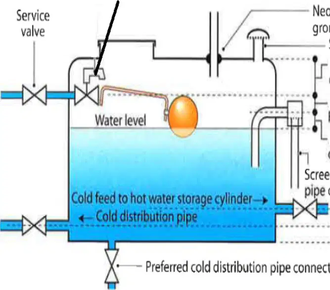
State the main considerations when installing a cold water cistern to section 2 schedule 7 paragraph 16, based on the diagram. Select all that apply.
Provide a screened vent with a neoprene sealing grommet around the vent pipe
Fit a service valve on the cold feed to allow isolation
Ensure a screened overflow/warning pipe that discharges below the water level
Position the preferred cold distribution pipe connection low on the cistern to promote circulation
Omit the float-valve connection to reduce turbulence
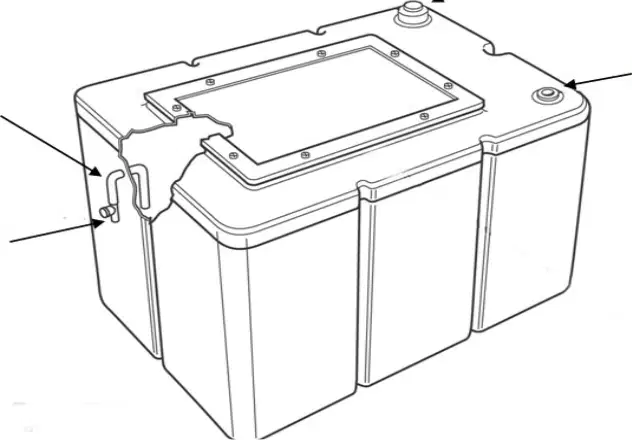
Label the diagram below. Item A on the plastic cold water cistern most likely indicates which feature?
Screened overflow/warning outlet on the cistern wall
Removable access lid/cover
Vent boss for the vent pipe
Cold feed outlet at the base
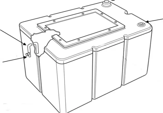
Label the diagram below. Item B on the plastic cold water cistern most likely indicates which feature?
Service valve location
Cold feed outlet spigot
Mounting lug or bracket on the cistern body
Float valve connection boss
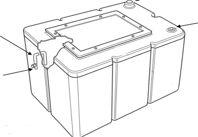
Label the diagram below. Item C on the plastic cold water cistern most likely indicates which feature?
Removable access lid/cover
Vent boss for the screened vent pipe
Overflow outlet
Cold distribution pipe connection
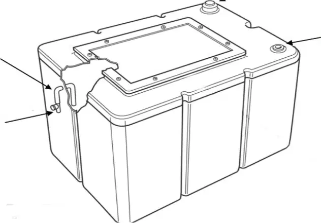
Label the diagram below. Item D on the plastic cold water cistern most likely indicates which feature?
Removable access lid/cover secured with screws
Float valve connection boss
Drain plug
Warning pipe clip position
State the requirements for a 1000L cold water cistern. Select all that apply.
Close-fitting insulated lid with access hatch
Screened vent and screened overflow/warning pipe
Rigid, level support base capable of carrying the full tank weight when full
Service valve on the cold feed and accessible isolation for maintenance
Use of solvent-based jointing compounds on plastic connections
Identify the tool used for drilling holes into the cold water cistern.
Hole saw with arbor
Wood chisel
Cold chisel and hammer
Twist drill without pilot
State which jointing material shouldn’t be used with plastic cold water cisterns.
PTFE tape
Rubber gasket
Solvent-based jointing compound (petroleum/oil-based paste)
Silicone sealant rated for potable water
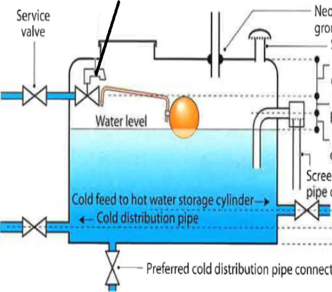
Identify in the diagram where you would install the distribution pipe to prevent stagnation.
High-level connection near the float valve
Mid-level connection just below the normal water line
Low-level connection at the base of the cistern, opposite the inlet
External bypass pipework
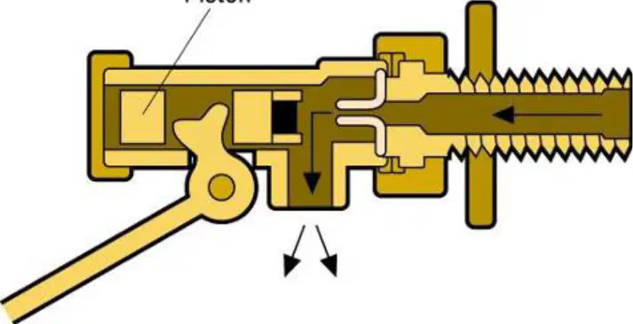
Identify the types of FOV below.
Portsmouth (piston type)
Equilibrium diaphragm type
Bottom-entry piston type
Top-entry diaphragm type
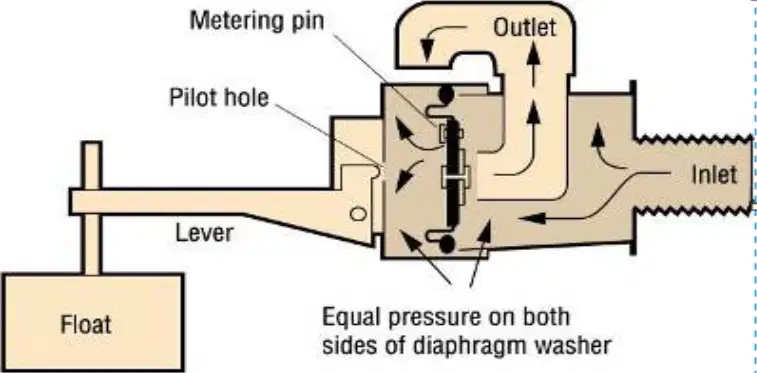
Identify the type of FOV shown.
Equilibrium diaphragm type
Portsmouth (piston type)
Bottom-entry piston type
Top-entry ball valve type
Describe the key contamination issues in plumbing systems. Select all that apply.
Backflow allowing contaminated water to enter wholesome supply
Cross-connections between potable and non‑potable circuits
Stagnation leading to microbial growth in stored or rarely used sections
Excessive water pressure causing noise and wear
Select the protective device you would install to protect category 1 water from category 2 fluids (e.g., hot water in a cylinder, discharge from a combi tap, softened water).
Single check valve on the supply
Double check valve on the supply
Reduced pressure zone (RPZ) backflow preventer
Type AG air gap above the receiving vessel
Select the protective device you would install to protect category 1 water from category 3 fluids (e.g., primary bath or shower water).
Single check valve on the supply
Double check valve on the supply
Reduced pressure zone (RPZ) backflow preventer
Type AG air gap above the receiving vessel
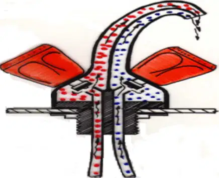
Identify which of the above taps would not require single check valves, and explain why.
Twin‑flow mixer tap, because hot and cold remain separated within the spout until discharge
Bi‑flow mixer tap, because hot and cold mix within the body before discharge
Both taps, because neither allows mixing before discharge
Neither tap, because both mix streams before reaching the outlet
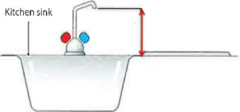
AUK3: This air gap is the distance between the outlet of a tap and the spillover level on a sink. Identify on which appliance this should be fitted to provide the air gap.
Bath
Wash basin
Kitchen sink
Bidet