
 Worksheets
Simbologia de Soldagem: Basic Symbols
Total questions: 104
Worksheet time: 52mins
In welding symbols, what does the notation L-P on the reference line indicate for a discontinuous weld?
Cord length (L) and pitch/center-to-center distance (P) of the intermittent weld
Leg size (L) and penetration (P) of a fillet weld
Location (L) on the arrow side and preparation (P) of the joint
Layer count (L) and process (P) used
A diagram shows a leader arrow pointing to a joint with a bracketed symbol { } followed by the numbers 5-10. According to the provided convention for discontinuous welds, what do these numbers represent?
5 mm leg size and 10 mm root opening
5 mm increment (cord length) and 10 mm pitch (center-to-center distance)
5 passes and 10 layers to complete the weld
5 mm penetration and 10 mm reinforcement
Which statement correctly distinguishes arrow side from other side information in basic welding symbols?
Information placed above the reference line applies to the arrow side; information placed below applies to the other side.
Information on the left of the arrow applies to the arrow side; information on the right applies to the other side.
Information near the tail always refers to the other side; only symbols near the arrow refer to the arrow side.
Arrow side details are written after a slash (/); other side details use parentheses.
Select all items that are correctly matched to their meaning in the discontinuous weld notation.
L denotes the cord length of each intermittent weld segment.
P denotes the pitch, measured center-to-center between weld segments.
{ } denotes a continuous weld all along the joint.
5-10 can exemplify L-P as 5 mm length and 10 mm center spacing.
According to the welding symbol note, where must the size or dimension be positioned relative to the symbol?
Always to the left of the symbol
Always above the reference line
Always to the right of the symbol
Centered beneath the symbol
In the illustrated fillet weld example labeled "Solda super dimensionada," what is primarily being communicated by the numeric values (e.g., 5, 10) shown near the welds?
Electrode classification numbers
Weld leg size or throat dimensions specified by the symbol
Ambient temperature during welding
Heat input measured in kJ/mm
Which statement best describes symbol localization in welding drawings?
Localization defines the material type used for welding.
Localization indicates the geometric place on the joint where the specified weld applies.
Localization measures the current (amperage) range used.
Localization refers to surface finish after welding.
When a welding symbol shows a pitch notation like "40 - 100" next to intermittent welds on a fillet joint, what does this typically indicate?
The bevel angle range for a V-groove
The minimum and maximum electrode diameters
The length of each weld segment and the spacing between segments
The hardness range after heat treatment
Which of the following is a basic weld symbol commonly used for a T-joint shown in the visuals?
Spot weld symbol
Seam weld symbol
Fillet weld symbol
Plug weld symbol
A triangular symbol placed on the reference line pointing to the joint most commonly represents which weld type?
Square groove weld
Fillet weld
Bevel groove weld
J-groove weld
In the visual where a dimension "5 - 10" appears next to the triangular weld symbol, how is this notation typically interpreted for an intermittent fillet weld?
5 mm leg size with 10° bevel angle
5 mm weld length with 10 mm pitch between welds
5 mm root opening with 10 mm reinforcement
5 mm electrode diameter with 10 mm travel speed
Choose all statements that correctly characterize chamfer-related notations in basic welding symbol tables.
Chamfer types describe edge preparations such as bevels or V-grooves.
Chamfer notations are irrelevant to fillet welds and appear only for plug welds.
Chamfer angles and root faces are often specified alongside weld symbols.
Chamfer is a localization marker rather than a joint preparation.
In a localization table for welding symbols, which entry would most likely indicate a weld on the arrow side of the joint?
A flag indicating field weld
A tail with process specification
A filled symbol placed on the arrow side of the reference line
A dashed line below the reference line indicating back gouging
Which combination correctly pairs joint type with a likely basic symbol shown in a vocabulary bank for welding?
T-joint — fillet symbol
Butt joint — V-groove symbol
Lap joint — plug/slot symbol
Edge joint — seam symbol
When the table indicates that dimensions are shown to the right of the symbol, what practical drafting rule should the welder or engineer follow?
Place size, length, or pitch values on the right side of the reference line near the symbol.
Always place material specifications on the left of the symbol.
Put process notes only in the tail of the symbol.
Avoid any numeric values near the symbol to reduce clutter.
Which notation best represents intermittent fillet welds with segment length and pitch specified?
A single number followed by the degree sign
Two numbers separated by a dash, such as 40 - 100
A fraction like 1/8 representing electrode diameter
Greek letters indicating heat input
In basic welding symbol vocabulary, what does the tail of the symbol most commonly contain?
Information about the welding process or specification
The measurement of reinforcement height
The base metal thickness
The inspection acceptance criteria only
Which statement aligns with the concept of symbol localization as applied to the arrow and other sides of the joint?
Localization dictates weld polarity settings.
Localization clarifies whether the weld is placed on the arrow side, other side, or both sides.
Localization only applies to chamfered joints.
Localization is synonymous with post-weld heat treatment.
Looking at the depicted T-joint where the fillet runs intermittently, which parameter would you adjust to change the spacing between weld segments without altering their length?
Leg size (a)
Pitch value
Bevel angle
Root face
In welding symbols for discontinuous welds, which statement correctly defines a coincident arrangement?
Weld segments on the arrow side and the other side alternate positions along the same joint.
Weld segments on the opposite side align directly with segments on the arrow side on the same joint.
Weld segments are continuous around the entire perimeter unless noted otherwise.
Select all statements that accurately describe an intercalated discontinuous weld as presented in the instructional material.
Segments on the opposite side and the arrow side are staggered along the same joint.
Segments on both sides coincide, sharing the same positions on the joint.
The notation shows repeated values such as 60 – 130 for increment and step.
Intercalated discontinuous welds cannot be indicated on T-joints.
A drawing shows discontinuous fillet welds labeled 60 – 130 on both the arrow side and the other side. Interpreting increment (L) and step (P), what does 60 – 130 indicate?
60 mm step and 130 mm increment along the joint.
60 mm increment length and 130 mm step spacing along the joint.
Total weld length of 60 mm distributed across 130 mm of joint.
A 60° angle and a 130 mm throat size for the fillet.
According to the description of interrupted welds, when the weld length is omitted from the symbol, what is implied?
The weld is intermittent and should be measured on site.
The weld spans the full length of the joint unless the all-around symbol is used.
The weld has total length of the joint provided there is no abrupt change in direction, except when the all-around symbol is used.
The weld must be repeated at equal intervals across the joint.
Which best defines an interrupted weld in the presented symbology?
A weld whose length does not extend over the entire joint and whose beginning must be dimensioned.
A weld performed on both sides of a joint simultaneously.
A weld continuous around the entire contour of the part.
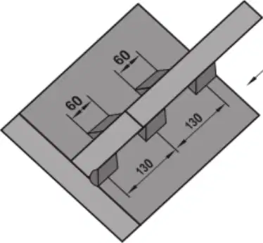
For discontinuous coincident welds shown on a T-joint diagram, what spatial relationship between segments should a fabricator expect?
Segments on both sides of the joint are offset from each other in a repeating pattern.
Segments on the opposite side directly mirror the arrow-side segments at the same positions.
Segments are continuous with no gaps along the joint.
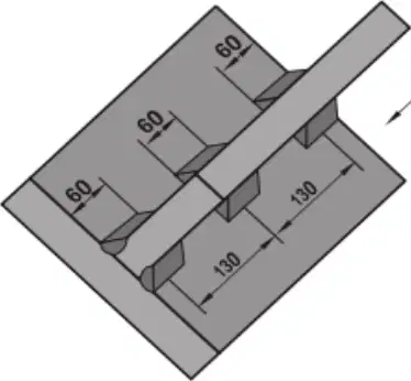
Choose the correct interpretation of the notation used for discontinuous intercalated welds on the diagram with repeated 60 – 130 values.
Equal increment and step values are applied on both sides, but the physical segments are staggered relative to each other.
Different values are used on each side, and segments coincide.
The numbers denote weld size and angle rather than spacing or segment length.
In the context of super-dimensioned welds, which pair of terms correctly matches the meanings given: Increment (L) and Step (P)?
L is the spacing between weld segments; P is the length of each segment.
L is the length of each weld segment; P is the spacing (pitch) between segment starts.
L is the total joint length; P is the throat size of the weld.
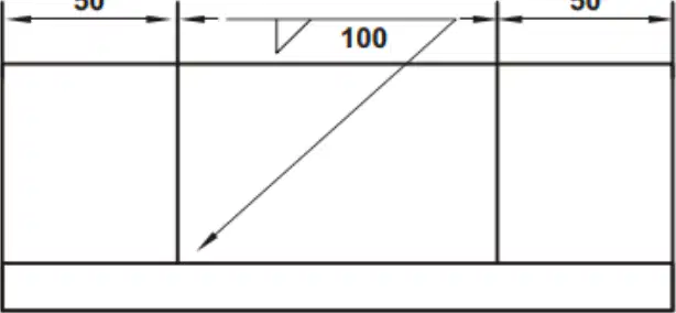
In welding notation, which description best defines a coincident discontinuous weld as illustrated in the top diagram where two weld segments share the same start and end positions?
Alternating weld segments placed on opposite sides of a joint with staggered starts
A series of intermittent welds on one side that are aligned across the joint so corresponding segments begin and end at the same locations
Continuous fillet weld around the entire joint length
Intermittent welds with variable spacing and unequal lengths along the joint
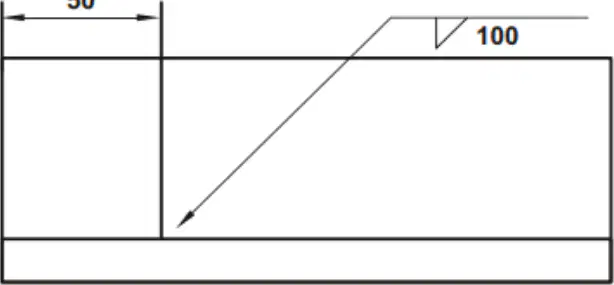
The interleaved discontinuous weld shown in the bottom diagram features two sets of intermittent welds. What distinguishes interleaved positioning from coincident positioning?
Interleaved welds are continuous and occur on both sides; coincident welds are intermittent on one side only
Interleaved welds are staggered so segments on opposite sides do not share the same start/end points; coincident welds are aligned across the joint
Interleaved welds are longer than coincident welds by definition
Interleaved welds require back-gouging; coincident welds do not
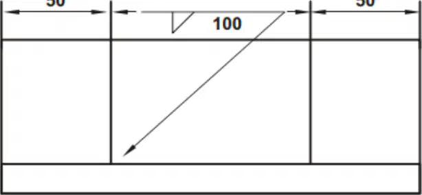
According to the dimensions shown, what is the spacing pattern for the coincident discontinuous weld segments along the joint length?
50 mm weld, 100 mm gap, 50 mm weld
50 mm gap, 100 mm weld, 50 mm gap
100 mm weld, 50 mm weld, 50 mm gap
Alternating 25 mm weld segments with 75 mm gaps
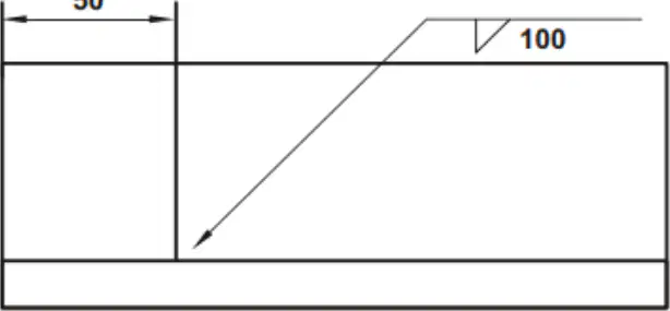
Select all statements that correctly describe interleaved discontinuous weld positioning as depicted.
Segments on opposite sides are staggered rather than sharing identical start/end locations
The arrangement reduces overlap of heat input at the same longitudinal positions
It is characterized by identical segment alignment across sides of the joint
It uses continuous welding across the entire length
In welding symbol notation, what does the omission of the weld length value "L" indicate for the joint?
The weld is intermittent with equal spaces between segments
The weld is continuous along the joint except at sharp direction changes
The weld is a spot weld limited to the first 50 mm
The weld must be double-sided by default
According to the welding symbol convention, where is the dimension or chamfer depth value "S" placed relative to the symbol?
To the right of the symbol, next to L-P
Above the reference line, centered
To the left of the symbol on the reference line
Below the arrow side only
In interrupted weld notation, what do the letters L and P represent when written as "L - P" on the right side of the symbol?
L is leg size and P is penetration depth
L is weld length and P is pitch (center-to-center spacing) between discontinuous welds
L is total joint length and P is process parameter pressure
L is layer count and P is pass number
Which statement best describes the placement of L-P values on a welding symbol for intermittent welds?
They must be placed to the left of the symbol with S
They are optional and placed only for fillet welds
They are placed to the right of the symbol to indicate segment length and spacing
They are placed below the tail to show process notes
A drawing shows a fillet weld symbol without L-P but with an S value. What is the most accurate interpretation?
Continuous weld along the joint, with specified chamfer depth/dimension S
Intermittent weld with unknown spacing
Spot welds placed randomly
Staggered intermittent welds on both sides
Select all elements that are explicitly indicated by the notation around the welding symbol as described:
S for dimension or chamfer depth on the left
L for length of each weld segment on the right
P for pitch (spacing) between centers of discontinuous welds on the right
Contour symbol placed to the far right to show total weld length
Which consequence follows if a joint requires intermittent welding but the designer fails to provide the L-P values?
The fabricator will assume a continuous weld along the joint
The welder will default to spot welding at random intervals
The inspection will require the smallest possible weld segments
The drawing is interpreted as a back-gouge requirement
In welding symbols, what does the number placed near the bevel (chamfer) symbol indicate? Choose the best answer.
The total joint thickness
The chamfer depth to be prepared before welding
The weld leg size of a fillet
The required filler metal diameter
A drawing shows a bevel symbol with the number 16 next to it. According to standard notation, what instruction does this convey to the fabricator?
Prepare a 16 mm groove width on both parts
Prepare a chamfer with 16 mm depth before welding
Deposit a 16 mm leg-size fillet weld
Ensure a projection height of 16 mm on the weld face
Which statement correctly describes projection height in welding notation?
It is the vertical distance the weld protrudes above the base surface when specified.
It is the angle of the chamfer edge.
It is the total width of the groove opening at the surface.
It is the amount of filler metal required per unit length.
A symbol shows a square groove with a vertical dimension arrow labeled 12. What does this most likely specify?
Groove width of 12 mm
Chamfer depth of 12 mm
Projection height of 12 mm
Continuous weld length of 12 mm
Consider a fillet weld symbol intended to be continuous along the joint. Which notation or feature communicates continuity?
A break in the reference line
The absence of pitch or length modifiers, indicating a continuous weld
A small circle at the elbow of the leader
A tail with process notes
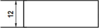
In the figure with three bevel symbols labeled 12, 16, and 25, what common aspect are those numbers marking across all examples?
The face reinforcement height
The chamfer preparation depth for each case
The weld throat thickness
The groove root opening
On the right-hand diagram showing a leader pointing to a joint with a small projection dimension, which choice best matches the specified measurement’s role?
It controls the groove angle.
It defines the projection height above the surface.
It sets the weld length increment.
It indicates the root gap to be maintained.
Which set of dimensions is correctly paired with its feature according to the section’s conventions? Select all that apply.
Chamfer depth: numeric value placed adjacent to the bevel symbol
Groove width: horizontal opening dimension across the joint face
Projection height: vertical protrusion dimension above the base material
Continuous weld: indicated by repeating lengths and pitches
Refer to the diagram showing a fillet weld symbol with a semicircular filled weld bead above a reference line and a small V-shaped indicator beneath it. In welding dimensioning, what does the "leg of the weld" represent?
The length of the weld along the joint
The thickness of the base metal plates
The perpendicular distance from the root to the toe of a fillet weld
The total deposited filler metal volume
In the diagram where a fillet weld is shown with numerical dimensions 7.6 and 2.5 adjacent to a semicircular bead, which value most likely denotes the weld leg size for the fillet?
7.6
2.5
Both 7.6 and 2.5 together
Neither value; leg size is not dimensioned
The left-hand visual states "Em projeção do lado oposto" (projection to the opposite side) and notes it is called penetration beyond the joint. What is being specified by this symbol?
The chamfer preparation depth on the arrow side
How far the weld should pass to the opposite side of the joint
The type of welding process to be used
The spacing between intermittent welds
On the right-hand diagram, a fillet weld symbol includes two short parallel lines next to the filled semicircle. According to the visual note in the following page, what do these parallel lines indicate?
Surface finishing requirement after welding
Additional backing strip to be removed
Specified penetration beyond the joint, accompanied by a numeric value
Chamfer preparation angle
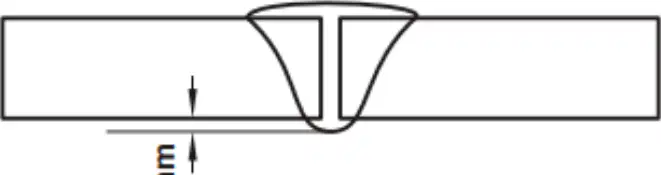
The page notes: "Este símbolo sempre vem acompanhado de outro; 1 mm e 2 mm" and shows two sections with 1 mm and 2 mm beneath the joint. In welding notation, what do the 1 mm and 2 mm values represent in these examples?
The weld leg length on the arrow side
The chamfer angle of the preparation
The amount of penetration projection beyond the joint to the opposite side
The spacing between multiple passes
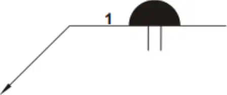
Which statements are correct based on the diagrams showing penetration symbols paired with numeric values? Select all that apply.
The penetration projection symbol must be paired with a numeric depth value.
A larger number (e.g., 2 mm vs. 1 mm) indicates greater penetration beyond the joint.
The symbol defines the weld process (e.g., TIG vs. MIG).
The symbol replaces the need to indicate weld leg size.
In welding symbolism, what does an opposite side projection indicate for a fillet weld when the tail or note specifies penetration beyond the joint?
The weld is applied only on the arrow side and stops at the joint line
The weld reinforcement is intentionally reduced on both sides of the joint
The weld is applied on the side opposite the arrow and is specified to penetrate past the joint
The symbol denotes surface treatment after welding without affecting penetration
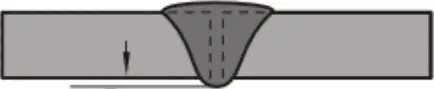
You are given a joint where the weld must penetrate beyond the joint line by 1.5 mm on the opposite side. Which statement best represents how this should be annotated in the welding symbol?
Place the penetration dimension on the reference line with no side designation
Indicate the fillet on the opposite side with the projection mark and add the 1.5 mm penetration dimension
Use a contour symbol only, since penetration is implied
Add the weld size as 1.5 mm and omit any projection indication
Which of the following symbols are considered combined symbols that always accompany another weld symbol when required? Select all that apply.
Contour symbol indicating flush or convex finish
Process designation in the tail (e.g., GMAW)
Weld-all-around circle
Finish method letter (e.g., grinding)
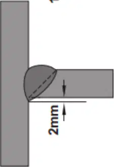
A T-joint requires a fillet weld on the opposite side with penetration beyond the joint of 2 mm. What is the most accurate implication for weld dimensions?
The leg size equals 2 mm because penetration replaces leg specification
The weld has its standard leg size, and 2 mm indicates additional projection past the joint line on the far side
Penetration beyond joint means the bead height is 2 mm above the plate surface
The opposite side indication is unnecessary when penetration is specified
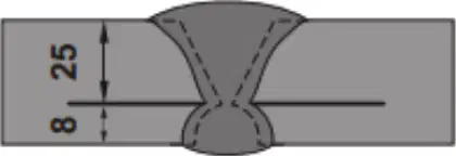
A butt joint symbol shows opposite side projection with 8 mm at the root and 25 mm penetration beyond the joint on the counter side. Which interpretation aligns with combined symbols usage?
The 8 mm value is a finish symbol and the 25 mm is the weld size
Both 8 mm and 25 mm are leg sizes of a double fillet weld on the arrow side
The projection and penetration dimensions are annotated along with the primary groove/fillet symbol, and may be paired with finish or contour symbols as needed
The numbers indicate heat input and are placed in the tail for process control
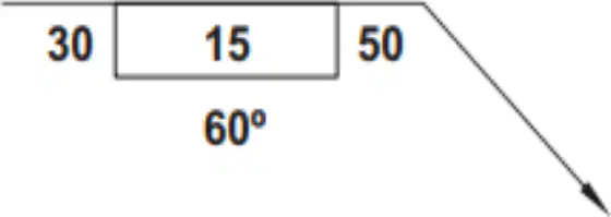
Refer to the plug/slot weld symbol shown: 30 [15] 50 with 60° noted below the box. Which dimension corresponds to the diameter of the hole or the width of the slot in this weld specification?
15
30
50
60°
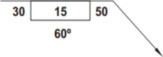
In the plug/slot weld notation, the value 50 is provided alongside 30 and 15. What does the 50 indicate?
Thickness of fill; omission means full fill
Spacing between hole centers
Countersink angle of the hole
Depth of the hole
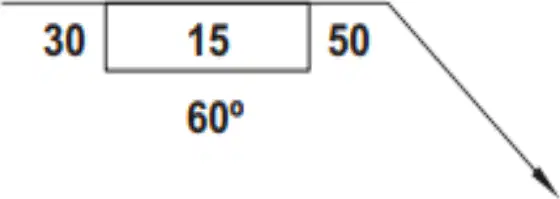
When a plug weld symbol shows 15 inside the rectangular box and no other thickness value is given, what does the 15 represent?
Diameter of the hole
Thickness of fill; omission means total fill
Length of the slot
Spacing between holes
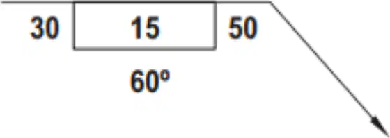
A plug weld specification includes “60°” below the symbol. What does this angle define according to the notation rules?
Bevel angle of a groove weld
Root opening of a fillet weld
Countersink (chamfer) angle of the hole
Torch travel angle for deposition
For slot welds, what additional information must be dimensioned on the drawing beyond diameter/width, spacing, fill thickness, and countersink angle?
Material type of the plates
Welding process used
Length of the slot
Number of passes required
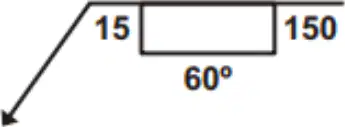
Using the example with three plug welds on an overlapping plate, the symbol shows 15 in the box and 60° beneath it, with a leader pointing to the joint. Which interpretation best matches this specification for each plug weld?
Each hole has a 15 mm diameter.
Each hole is countersunk to 60°.
Hole center spacing is 15 mm.
The fill thickness is specified as 15 unless omitted for full fill.
Define a plug weld in the context of welding symbols and fabrication requirements. Choose the best definition.
A weld made along the edge of two overlapping plates to form a fillet
A circular weld filling a round hole through one member to fuse it to the underlying member
A longitudinal weld deposited in a narrow groove between two plates
A surface overlay used to increase wear resistance on a plate
Define a slot weld according to welding practice. Select the most accurate description.
A weld deposited in a rectangular or elongated hole to fuse the member to the base underneath
A weld forming a U-shaped groove along a joint
A weld joining two tubes with a spiral bead
A weld that only tacks components before final welding
When specifying plug or slot welds, the hole or slot dimension refers to which feature?
The diameter of the plug or width of the slot opening prior to welding
The final surface bead height after filling
The length of the part being joined
The thickness of the backing member
Multi-select: Which parameters are commonly specified for plug or slot welds on drawings? Select all that apply.
Hole diameter or slot width and length
Center-to-center spacing between consecutive welds
Required fill thickness through the hole or slot
Chamfer angle at the hole or slot edge
Post-weld heat treatment temperature
In plug or slot welds, what does fill thickness indicate?
How much of the hole or slot depth must be filled with weld metal
The total thickness of both members being joined
The reinforcement height above the surface
The minimum throat of a fillet adjacent to the hole
A drawing notes: Plug welds Ø10 at 40 mm pitch, fill 3 mm, edge chamfer 45°. What does the 45° specify?
The angle of the weld bead to the joint
The chamfer angle cut at the hole edge prior to welding
The bevel angle of a butt joint nearby
The torch inclination during deposition
Multi-select: Which statements correctly distinguish plug welds from slot welds? Select all that apply.
Plug welds use round holes; slot welds use elongated holes
Plug welds cannot specify spacing, while slot welds can
Slot welds may require both width and length; plug welds are specified by diameter
Plug welds are only used on thin sheet; slot welds only on thick plate
Refer to the leftmost top diagram showing a T-joint fillet weld with a smooth convex surface and the dimension “20” indicated at the leg. Which weld face description best matches this symbol?
Rounded face (convex) fillet weld
Flat face fillet weld with no reinforcement
Concave face fillet weld
Half-rounded face groove weld
In the top-right diagram where a corner joint shows a fillet weld with a curved face, what additional notation would specify a half-rounded face rather than a fully rounded face?
A modifier indicating half-rounded face on the weld symbol
Adding an all-around circle at the reference line tail
Using a field weld flag on the leader
Placing the size on the other side of the reference line
Consider the middle-left diagram of a V-shaped joint with a single spherical contour at the root and a dimension marked as 10 at each leg. What does the dimension most likely indicate in this rounded-face fillet weld example?
The fillet leg size (S) for each side of the joint
The effective throat (E) excluding reinforcement
The reinforcement height above the face
The root opening between plates
In the middle-right diagram, a similar V-shaped joint shows a rounded bead and an added square frame leader. What is the likely purpose of this added notation in a weld symbol application example?
To specify a weld contour requirement (e.g., machining or grinding)
To indicate the joint is tack welded only
To mark the weld as intermittent with a pitch value
To denote a backing bar is required
Look at the bottom-left diagram showing two rounded fillet beads deposited sequentially on a plate with a vertical dimension of 9. Which interpretation aligns with weld symbol application?
Staggered intermittent rounded-face fillet welds with 9 mm leg size
Two-pass rounded-face fillet weld with 9 mm reinforcement
Concave groove welds with 9 mm root opening
Spot welds with 9 mm diameter
In the bottom-right diagram, two rounded fillet beads are shown with a triangular indication between them. What does the central triangular marker most plausibly represent in weld symbol conventions?
A stitch or intermittent pitch indicator between weld segments
A field weld flag showing on-site welding
A backing bar requirement at the root
A contour symbol for concave finishing
According to the text, which definition correctly describes the theoretical throat “S” of a fillet weld in an angular joint?
Distance between the joint root and the hypotenuse of the largest inscribed right triangle in the weld cross-section
Distance from the root to the external face including reinforcement
Distance from the root to the external face excluding reinforcement
Distance between the leg size and the root opening
Which statement correctly defines the real throat of a fillet weld, as described in the text?
It includes penetration and reinforcement in the measured distance from the root to the face
It excludes reinforcement while including penetration
It measures only the leg size without considering the face shape
It is the same as the theoretical throat for all welds
The effective throat, indicated as “E” in the text, is defined as which of the following?
Distance from the weld root to the face excluding any reinforcement but including penetration
Distance from the joint root to the hypotenuse of the largest inscribed right triangle
Distance measured along the reinforcement only
Distance between two intermittent weld segments
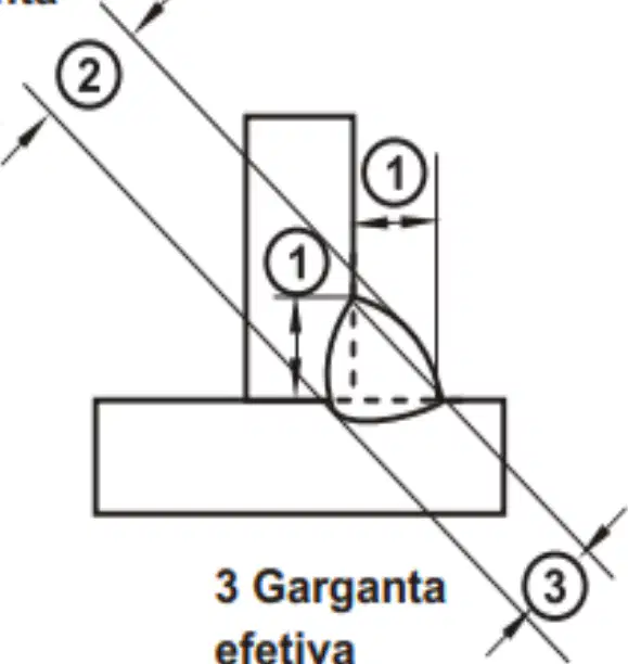
Refer to the right-side diagram with labels 1, 2, and 3. Which label corresponds to the effective throat, based on the illustration and text definitions?
Label 1
Label 2
Label 3
None of the labels
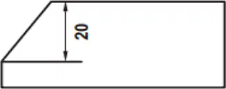
Refer to the butt joint diagram with the leader line and the notation 15(17). Based on standard welding symbol practice, what does the number in parentheses most likely indicate in relation to the primary weld dimension?
Alternate process thickness to be used only if the root pass fails
Secondary dimension such as reinforcement or overall weld size complementing the primary 15
Heat input value for the welding procedure specification
Inspection acceptance limit unrelated to geometry
In the joint preparation sketch showing a V-groove cut with a vertical dimension labeled 15, which interpretation aligns with applying weld symbols to specify preparation before welding?
The 15 indicates the groove angle in degrees for a single-V preparation
The 15 indicates the root opening in millimeters to be left before welding
The 15 indicates the groove depth in millimeters established during joint preparation
The 15 indicates the fillet leg size to be added after welding
Looking at the completed weld depiction with a V-shaped weld and a vertical dimension labeled 17, which statement best applies the weld symbol rules to communicate final weld dimensions?
The 17 represents the effective throat of the weld after reinforcement
The 17 represents the total weld height measured from the base metal surface to the top of reinforcement
The 17 represents the root face height prepared prior to welding
The 17 represents the backing strip thickness used during welding
When specifying both joint preparation and final weld dimensions for a butt joint, which combination correctly applies welding symbol notation similar to 15(17)?
Place 15 on the reference line to denote groove depth and list (17) to denote final weld size
Use 15 near the arrow to denote root gap and (17) above the tail to denote electrode diameter
Put 15 in the tail to denote heat input and (17) under the reference line to denote inspection level
Write 15 beside the joint to denote plate thickness and (17) in the field flag to denote field weld length
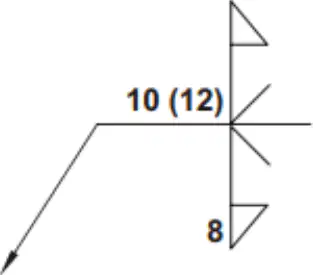
Refer to the T-joint diagram showing a seam weld along the base plate with callouts “10 (12)” and “8” on the weld symbol. In welding symbols for seam welds, what does the first number adjacent to the symbol typically indicate?
Weld length along the joint
Root opening between members
Weld spacing between intermittent segments
Electrode diameter used
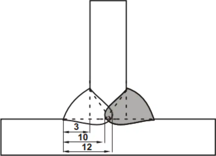
A seam weld symbol is specified with length 12 mm and pitch 10 mm. Which interpretation best matches an intermittent seam weld?
12 mm weld segments placed every 10 mm along the joint
10 mm weld segments placed every 12 mm along the joint
Continuous seam weld of 12 mm thickness
Alternating fillet and groove welds every 10 mm
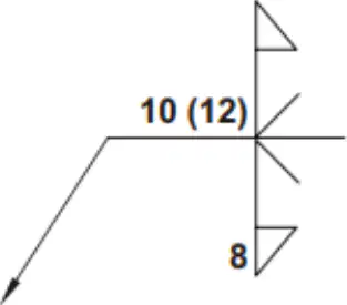
Which parameters are commonly conveyed by a seam weld symbol to fully define an intermittent weld on a T-joint? Select all that apply.
Weld length for each segment
Pitch or spacing between segments
Base metal tensile strength
Weld process code
In fillet weld terminology, which statement correctly defines the theoretical throat (S)?
The shortest distance from the root to the face of the weld if the fillet has a perfect right-triangle profile
The measured distance from the actual weld root to the weld face after cooling and inspection
The minimum throat considered for strength calculations after accounting for imperfections
The leg length specified on the welding symbol for a fillet weld
Which description best matches the real throat of a fillet weld?
Ideal geometric throat derived from designed leg lengths
Distance measured on the actual weld profile from the root to the face, reflecting true geometry
Adjusted throat used for design strength that excludes undercut and reinforcement
Average of the two leg lengths of the fillet weld
Effective throat (E) in fillet welds is typically used for which purpose?
To select electrode classification
To determine weld size on drawings
To calculate load-carrying capacity by using the minimum throat that is effective in resisting forces
To measure heat input during welding
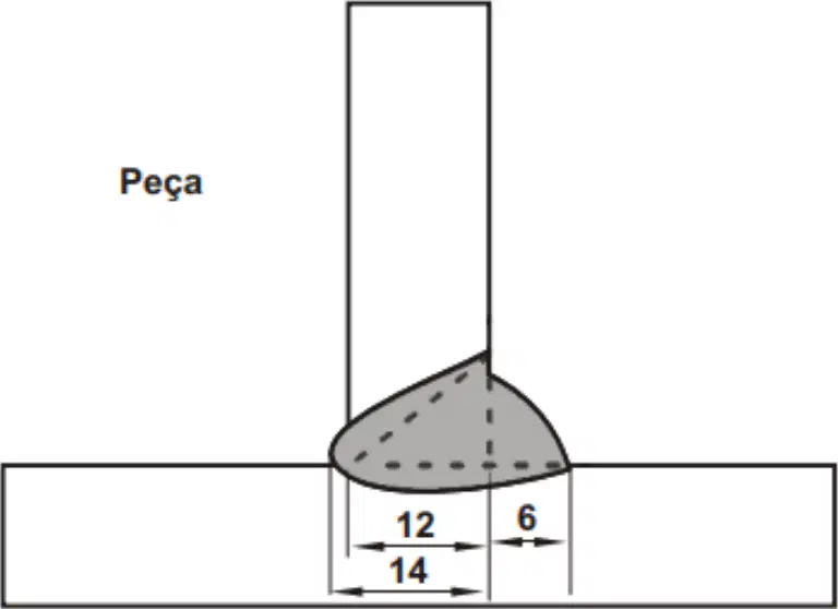
A T-joint fillet weld is shown with legs 12 mm and 6 mm and total leg extension 14 mm indicated. Based on fillet weld throat concepts, which statement is most accurate about its throat measures?
The theoretical throat S is computed from the idealized right-triangle formed by the design legs
The real throat equals the shortest actual distance from the weld root to the weld face on the shaded profile
The effective throat E will always equal the larger leg length (12 mm) regardless of discontinuities
The effective throat E is the minimum throat considered suitable for strength design after accounting for imperfections
Which pairing correctly matches fillet weld throat terms to their roles?
Theoretical throat (S): geometric ideal; Real throat: measured on actual profile; Effective throat (E): design minimum for strength
Theoretical throat (S): inspection tolerance; Real throat: electrode diameter; Effective throat (E): heat input metric
Theoretical throat (S): leg length sum; Real throat: average leg; Effective throat (E): always equal to leg size shown in symbol
When interpreting welding symbols for fillet welds, which parameter typically communicates the intended leg size, while throat concepts help evaluate actual and design strength?
The welding arrow length
The fillet weld size notation on the symbol (leg length)
The effective throat value measured post-weld
The theoretical throat value specified by the inspector
In butt weld terminology, which statement correctly defines the theoretical throat (S) for a complete-joint penetration butt weld? Choose the best option.
The shortest distance from the root to the centerline of the weld reinforcement
The shortest distance from the root of the weld to the face of the weld profile assuming perfect geometric filling
The measured thickness of deposited filler metal at the cap
The distance between the two bevel faces before welding
Which characteristics are associated with the real throat of a butt weld? Select all that apply.
It is the actual minimum distance from the root to the weld face after welding
It equals the theoretical throat for ideal, defect-free weld geometry
It can be reduced by lack of fusion or internal concavity
It is measured only from joint preparation dimensions prior to welding
The effective throat (E) of a butt weld is defined as:
The sum of theoretical and real throat values
The minimum throat that can be relied upon to carry design loads, considering imperfections and acceptance criteria
The largest throat dimension measured anywhere along the weld
The distance from the weld toe to the base metal surface
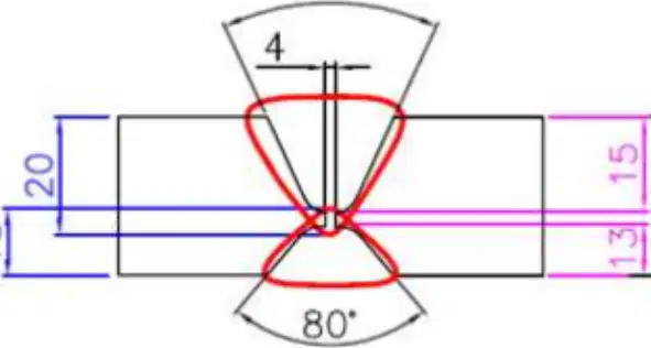
Refer to the double-U butt joint symbolized with included angles of 50° on the top side and 80° on the bottom side, with root face of 4 mm and preparation dimensions labeled 20, 18, 13, 15, and total thickness 32 mm. Which statement best relates these preparation angles to throat dimensions?
Larger preparation angles generally increase the theoretical throat by widening the weld face
Preparation angles primarily control access and fusion; the theoretical throat is governed by the shortest root-to-face distance for the final weld profile
Smaller angles always produce a larger effective throat regardless of weld quality
Angles have no influence on real throat since it is fixed by base metal thickness alone
When documenting butt weld dimensions on a drawing, which convention most directly communicates the throat-related requirements to the welder and inspector?
Specify only the bevel angles and root face, leaving throat implied
Indicate the required effective throat (E) or penetration requirement along with joint preparation, ensuring the minimum load-carrying section is met
Provide the real throat after welding as a note, measured on the first production part
List the theoretical throat (S) without tolerances and rely on visual inspection
Consider a butt weld where joint preparation is symmetrical and the weld is free of internal concavity, lack of fusion, and incomplete penetration. How do the throat definitions relate in this case?
Real throat < Effective throat < Theoretical throat
Effective throat = Theoretical throat, but real throat is larger
Theoretical throat = Real throat, and effective throat equals them under acceptance criteria
Effective throat is undefined without NDT
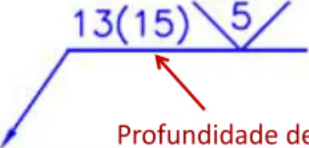
Refer to the diagram showing a single‑V butt joint with the notation 13(15) beside the bevel, a 60° included angle, and a 5 mm root face. What does the number outside the parentheses (13) specify for butt weld dimensioning?
Depth of weld penetration to be achieved
Total plate thickness before preparation
Depth of preparation of the bevel (groove)
Length of the weld segment
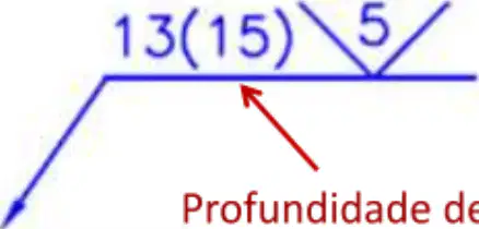
In the same butt‑weld diagram, the notation 13(15) indicates two dimensions. What does the number inside the parentheses (15) represent?
Depth of weld penetration
Root gap between plates
Electrode diameter
Bevel angle
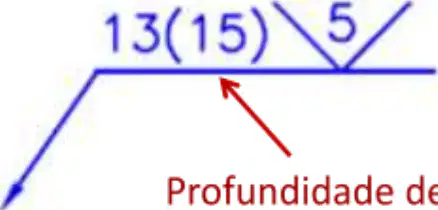
Which combination correctly interprets the butt‑weld geometry shown: included angle and root face?
60° included angle and 5 mm root face
45° included angle and 3 mm root face
60° included angle and 3 mm root face
45° included angle and 5 mm root face
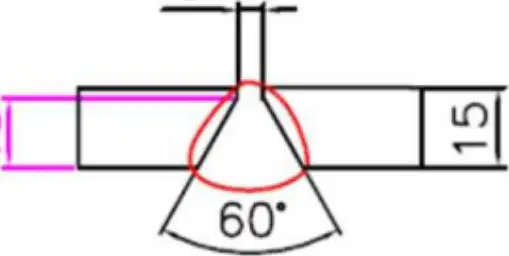
Refer to the right‑side fillet weld diagram showing a T‑joint with a triangular fillet, a 5 mm symbol above the weld, and a 60° arc at the bevel of the attached plate. What does the 5 mm value above the weld indicate for fillet welds?
Leg size of the fillet weld
Root opening of the T‑joint
Thickness of the base plate
Length of the weld segment
Based on both visuals, which statements are correct interpretations of weld dimensioning shown? Select all that apply.
For butt welds, the number outside parentheses denotes bevel preparation depth.
For butt welds, the number inside parentheses denotes required penetration depth.
A 60° value in the butt‑weld symbol indicates the included groove angle.
In the fillet weld example, 5 mm denotes the plate thickness, not the weld size.

