
 Worksheets
Plumbing components and foul waste worksheet
Total questions: 65
Worksheet time: 33mins
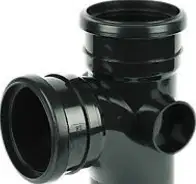
Identify the plumbing component shown. The image displays a black plastic soil fitting with a main straight-through body and a side boss forming a T-shaped branch.
Bossed branch (tee with side boss)
Short radius bend
Flexible rubber coupling
Bottle trap
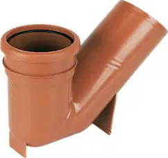
Identify the plumbing component shown. The image displays a brown drainage fitting forming an oblique junction where the branch joins the main line at approximately 45 degrees.
45° Y-branch (oblique junction)
Rest bend (swept 90°)
Pan connector
Reducer coupling

Identify the plumbing component shown. The image displays a white 90° connector with a black rubber sealing end designed to connect a toilet outlet to the soil pipe.
Pan connector (90°)
Bottle trap
Compression elbow for basin waste
Flexible rubber coupling
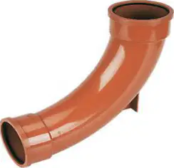
Identify the plumbing component shown. The image displays a brown long-radius 90° bend typically used as a rest bend at the base of a soil stack.
Rest bend (swept 90°)
Short radius 90° elbow
45° bend
Straight coupler
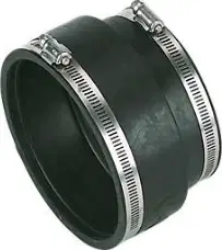
Identify the plumbing component shown. The image displays a black rubber sleeve with two stainless steel band clamps used to join pipes.
Flexible rubber coupling
Solvent-weld coupler
Compression straight connector
Pipe clip
Identify which document would specify where a soil stack should be installed in a building.
Approved Document H (Drainage and waste disposal) of the Building Regulations
RIDDOR (Reporting of Injuries, Diseases and Dangerous Occurrences Regulations)
BS 7671 (Wiring Regulations)
COSHH (Control of Substances Hazardous to Health)
Select the three diseases commonly associated with exposure to foul waste.
Cholera
Typhoid fever
Hepatitis A
Tuberculosis
State which item of PPE you would wear when working with foul waste.
Nitrile or waterproof gloves
Hearing protection (ear defenders)
High-visibility vest
Safety harness
When installing or removing cast-iron guttering, which two main legislations should you refer to? Select both.
Work at Height Regulations 2005
Manual Handling Operations Regulations 1992
Electricity at Work Regulations 1989
Personal Protective Equipment at Work Regulations 1992
State the primary purpose of a trap fitted to a discharge pipe.
Provide a water seal to prevent foul gases entering the building
Increase the flow rate of wastewater
Collect debris to aid cleaning
Act as a pressure relief device
Identify the depth of the trap seal below.
38 mm
50 mm
75 mm
100 mm
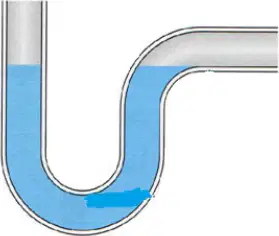
When running the discharge branch into a gully, what is the minimum trap seal depth?
25 mm
38 mm
50 mm
75 mm
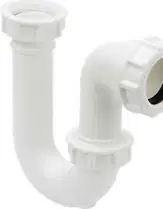
Identify the trap shown in the image.
P-trap
S-trap
Bottle trap
Running trap
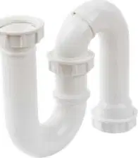
Identify the trap shown in the image.
P-trap
S-trap
Bottle trap
Anti-siphon trap
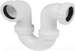
Identify the trap shown in the image.
Single-inlet P-trap
Double inlet sink trap
Bottle trap
Running trap
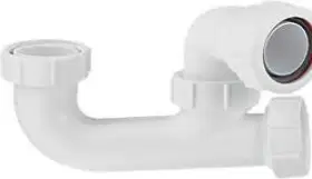
Identify the trap shown in the image.
Low-profile bath trap
Bottle trap
Running trap
P-trap
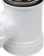
Identify the trap shown in the image.
Bottle trap
Anti-siphon trap
P-trap
Running trap
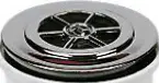
Identify the trap shown in the image.
Shower waste trap
Bottle trap
P-trap
Running trap
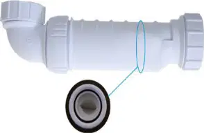
Identify this trap which externally looks like a bottle trap. Operation: When the trap is subject to syphonic conditions the automatic hydraulic action allows air to be drawn through the inlet of the trap and through the bypass columns, thus breaking the syphonic action.
Bottle trap
Anti-siphon bottle trap
P-trap
Running trap
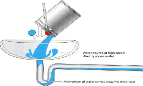
Identify the trap seal loss shown: water is poured at high speed directly above the outlet so the momentum of flowing water carries the water seal away.
Momentum loss from high‑speed discharge
Positive pressure in the stack
Capillary action by hair strands
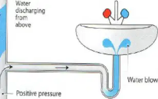
Identify the trap seal loss shown: water discharging from above creates positive pressure in a tight bend of the soil system or foot of stack, blowing water back into the appliance.
Positive pressure blowback
Evaporation
Capillary action
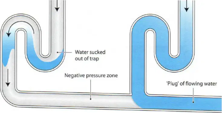
Trap seal loss — select all common causes illustrated across the worksheets.
Evaporation reducing seal depth
Wind‑induced pressure fluctuation at the terminal
Momentum loss due to high‑speed discharge near the outlet
Positive pressure blowback in the stack
Capillary action from material or hair across the weir
Place the soundness test in the correct order below. Steps listed: Visual inspection; fill all appliance traps with water include; fill all appliance traps with water include drain plugs; insert drain plug / inflatable bag; attach manometer to test to 38mm for 3 mins. Which step should be completed first?
Visual inspection
fill all appliance traps with water include
fill all appliance traps with water include drain plugs
insert drain plug / inflatable bag
attach manometer to test to 38mm for 3 mins
Place the soundness test in the correct order below. Steps listed: Visual inspection; fill all appliance traps with water include; fill all appliance traps with water include drain plugs; insert drain plug / inflatable bag; attach manometer to test to 38mm for 3 mins. Which step should be completed second?
Visual inspection
fill all appliance traps with water include
fill all appliance traps with water include drain plugs
insert drain plug / inflatable bag
attach manometer to test to 38mm for 3 mins
Place the soundness test in the correct order below. Steps listed: Visual inspection; fill all appliance traps with water include; fill all appliance traps with water include drain plugs; insert drain plug / inflatable bag; attach manometer to test to 38mm for 3 mins. Which step should be completed third?
Visual inspection
fill all appliance traps with water include
fill all appliance traps with water include drain plugs
insert drain plug / inflatable bag
attach manometer to test to 38mm for 3 mins
Place the soundness test in the correct order below. Steps listed: Visual inspection; fill all appliance traps with water include; fill all appliance traps with water include drain plugs; insert drain plug / inflatable bag; attach manometer to test to 38mm for 3 mins. Which step should be completed fourth?
Visual inspection
fill all appliance traps with water include
fill all appliance traps with water include drain plugs
insert drain plug / inflatable bag
attach manometer to test to 38mm for 3 mins
Place the soundness test in the correct order below. Steps listed: Visual inspection; fill all appliance traps with water include; fill all appliance traps with water include drain plugs; insert drain plug / inflatable bag; attach manometer to test to 38mm for 3 mins. Which step should be completed fifth?
Visual inspection
fill all appliance traps with water include
fill all appliance traps with water include drain plugs
insert drain plug / inflatable bag
attach manometer to test to 38mm for 3 mins
State the permissible pressure drop allowed on the soundness test.
0 mm
12 mm
25 mm
50 mm
Identify which substance you would use to identify where you had a leak during an air soundness test.
soapy water solution
food dye
engine oil
vinegar
Identify which building regulation soundness testing is covered in.
Part H (Drainage and waste disposal)
Part P (Electrical safety)
Part B (Fire safety)
Part L (Conservation of fuel and power)
Performance test. Steps: 1. Fill all the appliances on the system to their overflow levels. 2. Release the water from all the appliances simultaneously. 3. Flush the WCs at the same time. 4. Once all the appliances have finished discharging, check the trap seal depth in each appliance. How many times should the performance test be carried out?
once
twice
three times
five times
State the minimum trap seal depth after carrying out a performance test.
25 mm
38 mm
50 mm
75 mm
Identify what equipment you could use to test the trap seal depth.
ruler or depth gauge
manometer
pressure gauge
thermometer
Describe the test to check for self-siphonage trap seal loss. Which method correctly checks for self-siphonage?
Simultaneously discharge adjacent appliances and observe any reduction in trap seal depth
Fill the trap and leave it overnight without discharging appliances
Pressurize the system with air using a manometer
Add dye to the water and watch for color changes
Identify which appliance trap will block up due to hair and soap residue build-up.
bath or shower trap
kitchen sink trap
WC trap
floor drain trap
State which appliance trap will block up due to grease residue build-up.
kitchen sink trap
bath trap
WC trap
rainwater gully trap
State the three causes of the drain becoming blocked. Select all that apply.
excessive grease deposits within the pipework
hair and soap accumulation from bathing fixtures
tree root intrusion into underground drains
over-ventilation of the system
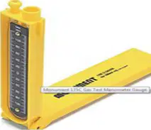
Identify the equipment shown in the image.
U-tube manometer
Vernier caliper
Spirit level
Flowmeter
Identify the equipment shown in the image.
Inflatable drain test plug kit
Sphygmomanometer
Air compressor
Rubber mallet

Identify the equipment shown in the image.
Drain rods
Rebar
Welding rods
Tent poles
Identify the equipment shown in the image.
Gully scraper
Stop valve key
Pipe cap
Float valve
Identify the equipment shown in the image.
Double worm screw drain attachment
Twist drill bit
Corkscrew bottle opener
Thread tap
Identify the equipment shown in the image.
Drain cleaning spoon
Ladle
Soil scoop
Trowel
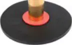
Identify the equipment shown in the image.
Plunger disc drain rod attachment
Pipe flange
Grinding wheel
Gasket washer
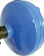
Identify the equipment shown in the image.
Handheld drum auger
Power drill
Heat gun
Spray gun
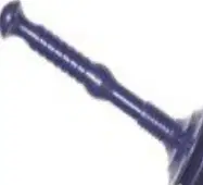
Identify the equipment shown in the image.
Accordion toilet plunger
Sink strainer
Pipe bender
Caulking gun
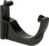
Identify the fitting shown: a single black plastic support that clips the gutter to the fascia board.
Gutter bracket
Gutter union
Stopend
Running outlet
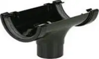
Identify the fitting shown: a gutter section with an outlet that connects vertically to a downpipe.
Running outlet
External angle
Stopend outlet
Gutter union
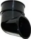
Identify the fitting shown: a short, swept bend used to form an offset from the outlet to the wall.
Offset bend (92.5°)
Downpipe shoe
Swept tee
Pipe coupler

State the type of guttering shown by the profile with approximate dimensions 110 mm wide by 80 mm deep.
Square‑line
Half‑round
Ogee
Deep half‑round

State the type of guttering shown by the profile with an approximately 112 mm semicircular cross‑section.
Half‑round
Square‑line
Ogee
Deep flow

State the type of guttering shown by the deeper U‑shaped profile marked about 115 mm.
Deep flow (deep half‑round)
Half‑round
Square‑line
Ogee
Select the three materials commonly used for residential guttering.
uPVC (plastic)
Aluminium
Cast iron
Concrete
Timber
What is the most common standard size pairing used for guttering and downpipe on typical domestic installations?
112 mm gutter with 68 mm downpipe
100 mm gutter with 75 mm downpipe
125 mm gutter with 80 mm downpipe
150 mm gutter with 100 mm downpipe
Identify the fall ratio typically used when setting out gutters so water runs to the outlet.
1:100
1:350
1:600
Level (0 fall)
State the maximum distance used for spacing gutter brackets along a straight run under normal conditions.
600 mm
750 mm
1 m
1.5 m
State the maximum distance for clipping a 68 mm downpipe vertically.
1.2 m
1.8 m
2.4 m
3.0 m
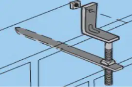
Identify the bracket shown: a metal spike with a semicircular cradle, driven into masonry to support the gutter.
Rise‑and‑fall bracket (drive‑in spike)
Top‑fix rafter bracket
Side‑arm rafter bracket
Downpipe clip
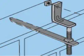
Identify the bracket shown: a metal strap fixing over the top of a rafter to support the gutter at the eaves.
Top‑fix rafter bracket
Rise‑and‑fall bracket
Side‑arm rafter bracket
Soffit bracket
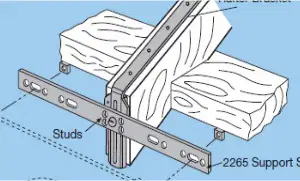
Identify the bracket shown: an adjustable side‑arm strap fixed to the side of rafters or studs to support guttering.
Side‑arm rafter bracket
Top‑fix rafter bracket
Rise‑and‑fall bracket
Downpipe clip
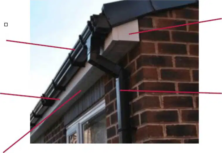
In the eaves photograph, name the board running along the roof edge behind the gutter.
Fascia board
Soffit board
Bargeboard
Wall plate
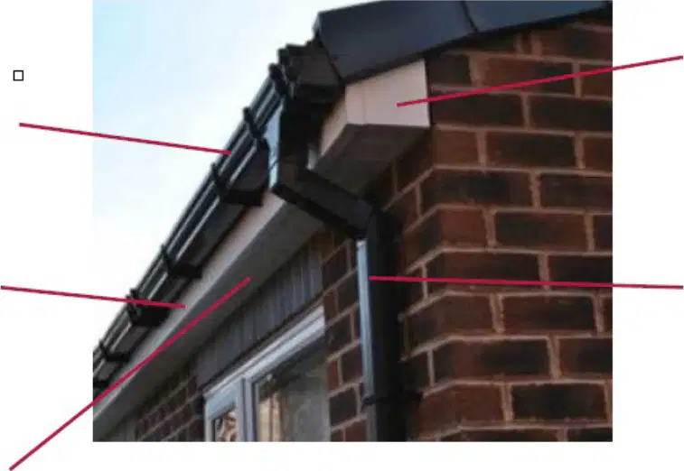
In the eaves photograph, identify the joint piece that connects two lengths of gutter in a straight run.
Union bracket
Running outlet
Stopend
External angle
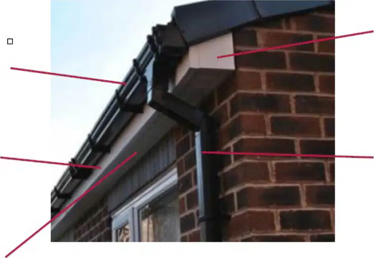
In the eaves photograph, identify the component that creates the offset from the running outlet to the downpipe.
Offset bend
Downpipe shoe
Swept tee
Cap end
For a 68 mm pipe, what is the recommended maximum spacing for vertical downpipe clips?
1.2 m
1.8 m
2.4 m
3.0 m
According to the note, what horizontal spacing should be used where heavy snowfall occurs?
750 mm
600 mm
900 mm
1 m

