
 Worksheets
Reinforced Concrete and Steel Design Problems
Total questions: 141
Worksheet time: 7hrs 3mins
A short reinforced concrete column is subjected to axial load and bending about its major axis. Given fcu = 45 MPa, fy = 500 MPa, fyv = 500 MPa, Es = 200,000 MPa, and cover to centroid of reinforcement = 55 mm. Explain the procedure to determine the axial load and moment capacities at balanced failure, stating key assumptions and equations you will use.
For the same column, without using an N–M interaction chart, outline a method to estimate the moment capacity when the ultimate axial compression is 3500 kN. Clearly state how you choose the neutral axis depth and compute forces in concrete and steel.
If the ultimate axial compression and major-axis moment are increased to 4000 kN and 780 kNm, respectively, describe how you would revise the section and transverse reinforcement, assuming only nominal shear reinforcement is required. Provide the steps and criteria for checking confinement and bar arrangement.
A simply supported rectangular beam of 8.0 m in centre span and 3.4 m end overhang spans carries unfactored loads: dead 25 kN/m (full length), imposed 18 kN/m on cantilevers AB & CD, and imposed 12 kN/m on span BC. Beam section: 300 mm wide × 520 mm deep, fcu = 45 MPa, fy = 500 MPa, cover to tension steel = 50 mm, use T25 or T32 bars. Describe how to construct the ultimate bending moment envelope and identify critical sections for hogging and sagging.
Using the beam data above, develop a flexural reinforcement design for the most critical sagging and hogging moments. State bar sizes/number selection logic, effective depth estimation, strength reduction, and detailing checks (minimum/maximum steel).
For the same beam, design the curtailment of flexural reinforcement only at the maximum hogging moment. Explain how you locate cut-off points, anchorage requirements, and any checks related to shear even if specific rules on shear capacity are ignored.
Describe and differentiate local buckling, global buckling, and lateral torsional buckling in steel members. Provide typical triggering conditions and how each affects capacity and design checks.
A tension member is formed by two parallel flange channels connected to a gusset by bolts: channel width 140 mm, flange thickness 17 mm, section depth 400 mm, web thickness 9.5 mm, bolt hole size 22 mm, gross area of one channel Ag = 8250 mm². With factored tension force Ft = 4200 kN and S355 steel, explain the procedure to check adequacy considering gross and net section, shear lag, and bolt-line deductions.
A UB 457×191×98 kg/m compression member of S275 steel, simply supported at both ends with braces at 0.25L, 0.5L, and 0.75L preventing minor-axis lateral displacement, total length 10.0 m. Explain how to check adequacy under factored axial load corresponding to nominal dead 950 kN and live 720 kN. Include slenderness evaluation, effective length, buckling resistance, and interaction where needed.
A steel beam ABCD is subjected to two normal ultimate point loads with lateral restraints at A and D (compression flange fully restrained against rotation at A; D under nominal torsional restraint; effective lateral restraint only at B and C). Design the beam for flexure to the nearest UB section of Grade S355. Detail the steps: bending moment evaluation, section classification, plastic/elastic capacity, and effect of λLT = 0.9λ with λ = LE/ry on lateral torsional buckling.
For the beam in the previous question, discuss the design changes if effective restraints at B and C are removed. Explain how the unrestrained length affects lateral torsional buckling, required section size, and any need for stiffeners or added restraints.
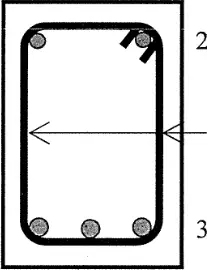
Figure 1a shows a reinforced concrete beam section 265 mm wide and 650 mm deep with 2T16 top bars, 3T32 bottom bars, and T10 stirrups at 200 mm spacing. Explain how the placement and sizes of reinforcement address bending and shear demands in this beam, and propose one modification if the beam experiences higher shear near supports.
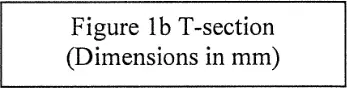
For the T-beam in Figure 1b (flange width 1350 mm, flange thickness 100 mm, web width 360 mm, effective depth to steel As of 55 mm cover from soffit, total depth 640 mm), determine whether the section will behave as a T-section or as a rectangular section under positive bending and justify your decision using flange dimensions relative to the neutral axis location.
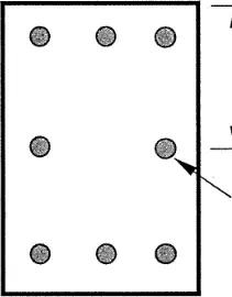
Figure 2 indicates a rectangular column section 425 mm by 600 mm reinforced with 8T25 bars arranged around the perimeter. Describe a rational tie (link) layout to satisfy confinement and buckling restraint, and explain how bar spacing and cover influence axial capacity and ductility.

In Figure 3, a continuous beam spans A–B–C–D with two interior supports at B and C. Spans AB and CD are 3.4 m; span BC is 8.0 m. Outline a step-by-step approach to estimate qualitative bending moment signs and relative magnitudes at A, B, C, and mid-spans assuming uniform gravity loading. Identify the likely critical negative and positive moment regions.
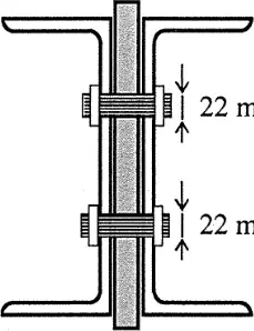
Figure 4 shows two parallel flange channels connected to a central gusset plate with two 22 mm bolt holes. Evaluate the load path for axial tension and shear through the bolts and plate. Discuss potential failure modes and recommend detailing to improve connection ductility and slip resistance.

Figure 5 depicts a beam simply supported at A and D with point loads of 55 kN at B and 100 kN at C located at 5.6 m, then 3.8 m, then 2.5 m segments along the span. Compute the support reactions at A and D using static equilibrium, showing your equations and final numerical results.

Using the reaction results from Figure 5, sketch or describe the shear force diagram and indicate the value of shear just to the left and right of points B and C. Explain how these jumps relate to the applied point loads.
A water-retaining structure experiences earth and water pressure that is beneficial due to inward hydrostatic action. Explain how the partial safety factor for earth/water pressure should be treated in load combinations and why it must not exceed 1.0.
Compare the partial safety factors for adverse dead load and adverse imposed load in combination 1 (dead and imposed with earth/water pressure). Discuss the implication of their difference on ultimate load effects.
Discuss how differential settlement influences the choice of partial safety factor for earth and water pressure in the load combinations and provide the design rationale.
Evaluate the material partial safety factors γm for reinforcement, concrete in flexure, and concrete shear without shear reinforcement at ULS and explain how these values reflect different reliability considerations.
A beam is designed for both ULS and fire limit state (FLS). Justify how bond strength γm values differ between ULS and FLS and what this implies for detailing.
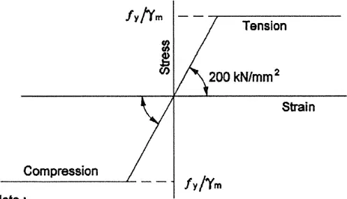
Explain the key features of the short-term design stress–strain curve for reinforcement, including the role of fy/γm and the plateau at 200 kN/mm².
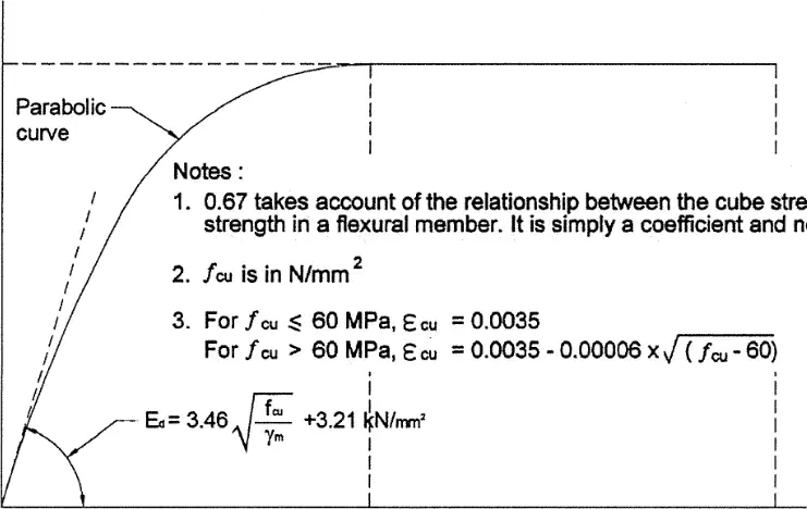
Summarize the concrete short-term stress–strain relationship, including the use of 0.67 fcu/γm, the strain at peak, and how ecu varies with fcu.
For a normal-weight concrete with fcu = 50 MPa, compute ecu and discuss how it affects the simplified stress block depth in flexural design.
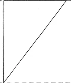
Describe the simplified stress block used for beams at ULS, including the rectangular stress magnitude and the strain limits, and explain its purpose in flexural calculations.
Explain the code limitations on neutral axis depth x relative to effective depth d for different concrete strengths and why these limits change with fcu.
Define the non-dimensional moment parameter K = M/(bd² fcu). Discuss how K is used to decide whether compression reinforcement is required and relate it to K′ limits with and without redistribution.
For fcu = 50 N/mm² and redistribution not exceeding 10%, state K′ and explain the design consequence if K = 0.18.
Discuss how moment redistribution exceeding 10% modifies K′ using the βb terms and explain the physical meaning of βb in this context.
A singly reinforced beam with fcu = 45 N/mm² has K = 0.10. Determine whether compression reinforcement is required and outline the steps to compute z and x using the relevant expressions.
When K > K′, describe how to determine the area of compression reinforcement As′ and present the combined steel requirement formula.
Explain the check on maximum compression stress in reinforcement relative to 0.87 fy, including how the strain ratio d′/x triggers use of the reinforcement stress–strain curve.
A rectangular concrete beam of breadth b_v = 300 mm and effective depth d = 500 mm resists a design shear force V = 180 kN at a section away from supports. Calculate the design shear stress v and state whether shear reinforcement must be provided if v ≤ 0.5 v_c, where v_c = 0.67 N/mm² for the member. Explain your reasoning based on code limits.
For a flanged beam, which breadth should be used in calculating design shear stress v, and why is this choice appropriate for shear at a cross-section?
Describe when it is satisfactory to omit minimum shear links in members of minor structural importance and lintels. Include the condition on maximum design shear stress.
A beam has v_c = 0.62 N/mm² from the code table. Determine the minimum area of shear links A_sv required per unit spacing if links only are provided, given γ_r = 0.4 and f_yv = 460 N/mm². Use the code expression A_sv ≥ γ_r b_v s v / (0.87 f_yv) and explain variables.
Explain the limit on the proportion of shear resistance that may be provided by bent-up bars when combined with links, and justify the structural rationale.
Using the tabulated values, estimate v_c for a beam with effective depth d = 250 mm and 100 A_s/(b_v d) = 1.00. State any table notes that constrain the use of these values.
At a monolithic beam–column junction with nominal top steel provided to control cracking at the support, explain how v_c should be calculated and where the top steel should extend.
State the spacing rules for shear links along and across the span of a beam. Include both the maximum spacing along the span and the limit relative to tension bars at right angles.
Derive v_c' for a section subject to shear and axial compression using the given expression and define all variables. Discuss the limitation on Vh/M.
Provide the adjusted limit on allowable shear stress to avoid shear cracking prior to ULS when axial compression is present, using the code relationship. Clarify when v_c is replaced.
Discuss the maximum permitted shear stress v relative to concrete strength and give the two alternative limits. Explain the design consequence when v exceeds v_c' or v_c.
For rectangular columns in compression, state when a shear check is not required and specify the condition involving M/N and v.
Outline general design guidance for solid slabs supported by beams or walls, referencing which beam provisions apply and any additional clauses.
Explain the simplification of slab load arrangements for one-way spanning slabs and list the three conditions that must be met for using the single-load case of maximum design load on all spans.
Given d = 200 mm and 100 A_s/(b_v d) = 0.75, read v_c from the table and comment on how increasing d to 300 mm alters v_c for the same reinforcement ratio.
A continuous one-way slab has approximately equal spans with uniformly distributed load. End supports are continuous. Using the coefficient method, estimate the ultimate negative bending moment at the first interior support in terms of F·l (F = ultimate uniformly distributed load per unit area, l = span). Explain your reasoning briefly.
For a one-way slab with simple support at the outer end and continuous interior supports, select the correct set of ultimate bending moment coefficients at the middle interior spans and interior supports (in terms of F·l).
A designer is checking shear in a solid slab. The design shear stress v is computed from V, b, and d. Choose the correct expression and state the upper limit that must not be exceeded irrespective of provided shear reinforcement.
A one-way slab with continuous end support under UDL has an ultimate shear at the outer support. Which coefficient should be used, and what is the typical change when moving to the first interior support?
Explain how reinforcement curtailment may be applied in continuous one-way slabs designed using bending-moment coefficients. Specify the governing clause interaction at a high level.
Explain the deemed-to-satisfy approach for limiting deflection in reinforced concrete members and identify situations when explicit deflection calculation becomes necessary.
A simply supported rectangular beam must satisfy deflection control using span-to-effective depth ratios. State the basic limit and discuss how this limit changes for flanged beams and one-way solid slabs under the same support condition.
Compare span-to-effective depth ratio limits for continuous members: rectangular beams, flanged beams, and one- or two-way solid slabs. Explain the structural reasoning behind why continuous systems allow greater ratios than simply supported members.
For end spans of continuous members, report the basic span-to-effective depth ratios for rectangular and flanged beams, and for two-way slabs. Clarify the special note that applies to two-way slabs in end spans.
Describe how long spans influence the use of tabulated span/depth ratios and provide the adjustment recommended for spans exceeding 10 m, including the exception for cantilevers.
Define the modification factor applied to span/effective depth ratios due to tension reinforcement. Present the governing equation and identify the parameters involved.
Using the modification factor table for fy = 250 MPa, estimate the factor when the service stress fs is 200 MPa and M/(bd^2) = 2.0. Explain how this affects the allowable span/depth ratio from the basic table.
A continuous beam has midspan design ultimate moment not known for redistribution. Explain how to estimate service stress fs for use in the modification factor table and justify the assumption suggested.
Outline the practical considerations and limitations for shear reinforcement in slabs mentioned alongside deflection criteria, and explain why these notes matter for slab design.
Plan a design check for a two-way slab spanning 8 m by 6 m, continuous along the 8 m edges. Detail the span/effective depth ratio to use, any special notes to apply, and how you would modify the ratio based on tension reinforcement stress at service.
A rectangular concrete beam with fy = 500 N/mm² is designed mainly for flexure. Determine the minimum percentage of tension reinforcement required and explain the implication for bar selection in a 300 mm × 500 mm section.
For a flanged T-beam with web breadth bw and overall depth h, fy = 250 N/mm², what minimum percentage expression governs tension reinforcement when the flange is in tension? Provide the percentage value and how it applies to sizing.
Explain the maximum area limits for tension and compression reinforcement in beams and how laps influence the effective area within a layer.
A beam near the tension face requires bar spacing checks. State the formula that limits clear horizontal distance between adjacent bars (or groups) and identify the variables. Include the absolute cap.
Describe the minimum clear distance between parallel bars or layers to ensure placement and bond. Provide the rule with aggregate size consideration.
Side bars are required in a beam with overall depth 800 mm to control cracking. Determine the minimum size requirement in the side faces and the distribution length along the depth.
Curtailment of tension reinforcement is planned in a flexural member away from supports. Specify the minimum extension distance beyond the theoretical cutoff and list additional checks for design ultimate load.
Define the minimum lap length for bar reinforcement, including welded fabric, and outline the adjustments when laps occur at the top of a section with limited cover or at a corner with small clear distances.
A one-way slab with fy = 250 N/mm² requires minimum longitudinal reinforcement per direction. Calculate the minimum percentage and explain secondary transverse reinforcement provision relative to principal reinforcement.
State the maximum spacing limits for principal and secondary reinforcement in slabs in general areas and how these limits change in zones of concentrated loads or maximum moments.
Detail the anchorage of span reinforcement into end supports for simply supported slabs or end supports of continuous slabs. Include the allowance for low design shear stress at the face of support.
Negative moments may occur due to partial fixity at slab supports. Specify the minimum top reinforcement to control cracking and the required anchorage into the support.
At an intermediate support of a slab, describe the requirement for bottom reinforcement continuity through the support and its relation to the mid-span design.
Design a rectangular beam section 300 mm wide by 600 mm effective depth with fy = 250 N/mm². Compute (a) the minimum tension reinforcement percentage, and (b) the maximum allowable reinforcement area limit. Summarize how these inform initial bar layout.
Propose a bar arrangement for a one-way slab 150 mm thick using fy = 500 N/mm² that satisfies minimum reinforcement and spacing both for principal and secondary directions in general areas. Show calculations and a compliant set of spacing values.
A rectangular concrete column has a gross cross-sectional area of 0.4 m². Determine acceptable ranges for the total area of longitudinal reinforcement if design limits require not less than 0.8% and not more than 6% for vertically cast columns. Show your calculation and state whether a design proposing 0.020 m² is acceptable.
Which statement best describes minimum bar sizes and quantities for longitudinal reinforcement in typical columns?
For a polygonal column cross-section, how should longitudinal bars be distributed to ensure stability?
State the three limiting criteria for spacing of transverse reinforcement along a column and explain why using the least of these controls performance.
Choose the smallest acceptable diameter for transverse reinforcement links in a column where the largest longitudinal bar is 24 mm diameter. Assume welded mesh is not used.
A change in column size causes the direction of longitudinal bars to shift with a 1 in 10 inclination. Should the effects of bar direction change on transverse reinforcement spacing be ignored?
Explain the anchorage requirements for links and crossties in rectangular or polygonal columns, including hook angles and alternation along the longitudinal bars. Provide rationale for these detailing rules.
When supporting corner bars and alternate bars in the outer layer with links, what is the maximum included angle around the bars for adequate enclosure?
Compute the design ultimate anchorage bond stress f_bu for ribbed bars in tension when the characteristic compressive cube strength f_cu is 40 N/mm² (limit ≤60). Use β = 0.50. Show steps.
Match each bar type and stress state with the appropriate β coefficient for anchorage bond calculations.
Using lb ≥ f_s d / 4 f_bu and f_s = 0.87 f_y, estimate the minimum ultimate anchorage bond length (as multiples of bar diameter) for grade 40 concrete with ribbed bars in tension when f_y = 500 N/mm². Compare your result with tabulated values and discuss any differences.
From the table of ultimate anchorage bond lengths, which option correctly gives the multiples of bar diameter required for grade 50 concrete in compression for fabric reinforcement?
A one-way slab requires 6 bars of 16 mm diameter in the tension zone. Using reinforcement bar area per number of bars, determine the total steel area provided and comment on whether this meets a minimum area target of 1000 mm².
You plan a distribution reinforcement layout with 12 mm bars spaced at 225 mm. Estimate the reinforcement area provided per metre width and compare it to using 10 mm bars at the same spacing. Which option provides more area and by how much?
A beam requires shear reinforcement with two-legged stirrups. If 10 mm stirrups are used at 200 mm spacing, compute the shear steel area per millimetre of beam length, and evaluate the change if spacing is reduced to 150 mm.
Design a bar arrangement to achieve approximately 5000 mm² of reinforcement using equal-diameter bars from the table. Propose two feasible configurations with justification.
For a T-beam, you can pick either 12 mm two-legged stirrups at 250 mm spacing or 16 mm two-legged stirrups at 275 mm spacing. Compare the shear steel area per millimetre of beam length for the two options and recommend which provides greater shear capacity.
Using the diagram of the column design chart (d/h = 0.90), explain the step-by-step procedure to estimate the required reinforcement ratio for a rectangular reinforced concrete column subjected to a given axial load ratio bhfcN and bending moment ratio bh2fcM . Include how you navigate the interaction curves and any assumptions needed for interpolation.
Which parameter primarily shifts the family of curves in the column design chart and must be matched before reading capacity:
A column is designed using the chart with d/h = 0.90. If the axial load ratio is increased while keeping the reinforcement ratio constant, what general trend occurs to the allowable moment capacity ratio read from the interaction curves?
For a hot-rolled I-section web, the code requires checking shear buckling if the web depth-to-thickness ratio d/t exceeds 70ε. Explain what ε represents and how it relates to the steel’s design strength.
An all-rolled I-section flange in compression due to bending has width-to-thickness ratio b/t. State the classification limits for plastic, compact, and semi-compact behavior and describe the implication of exceeding the semi-compact limit.
The web of an I-section at mid-depth in bending is controlled by d/t. Provide the limits for plastic, compact, and semi-compact classes and state what classification applies when d/t is larger than the semi-compact limit.
In an I- or H-section with equal flanges under axial compression, the web classification includes the term r2 = Fc/(Ag p_yw). Explain the meaning of each variable and how r2 affects the web classification limit.
Given S275 steel, list the design strengths py (N/mm²) for thicknesses 16, 40, 80, and 150 mm and explain the trend with increasing thickness.
A rolled I-section web has shear area Av ≈ tD. Derive the minimum shear capacity Vc using the code expression and state when this check is sufficient without shear buckling verification.
Under low shear (V ≤ 0.6Vc), state the moment capacity expressions for Class 1–2, Class 3, and Class 4 sections and explain the role of S, Z, Seff, and Z_eff.
For lateral-torsional buckling, define the effective length LE for a simple beam with compression flange restrained against lateral movement at supports but free to rotate on plan and with ends under nominal torsional restraint.
State the effective length LE for a beam with compression flange fully restrained against rotation on plan at its end supports, and explain why it differs from case (a).
Define the buckling resistance moment Mb for a beam segment and state the relationship involving m_LT, Mx, and Mb that must be satisfied. Explain when m_LT can be conservatively taken as 1.
Provide the expressions for buckling resistance moment Mb for Class 1–2, Class 3, and Class 4 sections, and explain the role of pb, Sx, Zx, Seff, Z_y,eff, and py_r/py.
Explain how section classification (plastic, compact, semi-compact, slender) influences which modulus (S, Z, Seff, Z_eff) and design strength (py vs py_r) are used in moment and buckling capacity calculations.
A hot-rolled I-section beam uses S355 steel with thickness 40 mm. Determine ε, then state whether a web with d/t = 95 requires shear buckling check and compute Vc with D = 500 mm and t = 10 mm. Show steps.
Derive an expression for the nominal moment capacity Mc of a fully restrained steel beam section in terms of yield strength fy and plastic section modulus S, and explain when it is appropriate to substitute the elastic modulus Z instead of S. Include implications for compact, noncompact, and slender sections.
A simply supported I-beam of steel grade S355 has a plastic modulus S = 6.0×106mm3 and elastic modulus Z = 5.1×106mm3 . Determine Mc for compact behavior and discuss the reduction required if the flange local buckling controls, indicating how Z would alter the capacity. Assume fy = 355N/mm2 .
Given a beam segment with intermediate lateral restraint at quarter points, outline a step-by-step procedure to compute the equivalent uniform moment factor mLT using the general case formula mLT = 0.15M2 + 0.5M3 + 0.15M4 divided by Mmax, and justify why mLT must be ≥ 0.44.
For a segment with positive end moments and no intermediate lateral restraint, compare how different load distributions lead to tabulated mLT values of 0.85, 0.93, and 0.74. Explain what the differences imply for LTB sensitivity and design conservatism.
A cantilever without intermediate lateral restraint has mLT = 1.00. Explain why this value is appropriate for design and discuss how end moment sign and load application location affect LTB risk in cantilevers.
Define the maximum permissible slenderness ratio λL0 for negligible buckling effect as shown in the bending strength table, and explain how exceeding λL0 influences the selection of pb (bending strength) for rolled sections.
Using the bending strength table for rolled sections, estimate pb for S355 steel at λLT = 100 and describe the trend of pb with increasing λLT. Provide reasoning linking the trend to LTB and cross-section behavior.
Propose a design workflow to check a laterally unrestrained beam: determine LE, mLT, slenderness λLT, bending strength pb, and final moment capacity. Highlight decision points where section class (compact/noncompact/slender) and restraint spacing alter the outcome.
A beam segment has M2 = 120 kNm, M3 = 180 kNm, M4 = 140 kNm, and maximum moment Mmax = 200 kNm. Compute mLT using the general case formula and evaluate whether the computed value satisfies the minimum requirement. Discuss implications for capacity reduction due to LTB.
A steel tension member is connected through one leg using bolted connections. The gross sectional area Ag of the angle is 1200 mm², and the connected leg area a1 is 300 mm². The yield strength py is 275 MPa. Using Ae = Ag − 0.5 a2 and a2 = Ag − a1, calculate the tension capacity Pt. Show your steps and units.
Explain why members with eccentric connections may require a reduced tension capacity compared to concentric connections. Identify the key behavior causing the reduction and how design accounts for it.
For a welded single angle connected through one leg, write the expression for tension capacity Pt in terms of py, Ag, and a2, and define a2. Do not compute a number.
A double angle is connected on both sides of a gusset plate with bolted intermediate connections. State the formula for Pt in terms of py, Ag, and a2 for this configuration, and explain why the deduction on Ae differs from single-angle cases.
The effective net area ae for tension is determined from ae = Ke an ≤ ag. Describe the role of Ke and list typical values for steel grades S275, S355, and S460. Explain what happens if ae exceeds ag.
A compression member has pin-ended conditions approximated by rotation free and transition fixed at both ends. Using the effective length table, state the recommended K value and explain what ‘effective length’ means for buckling calculations.
Compute the slenderness ratio λ for a column with effective length Le = 3.0 m and radius of gyration r = 60 mm. Comment on whether the member is likely in the inelastic or elastic buckling range for typical structural steel.
For Class 1–3 cross-sections in compression, express Pc in terms of Ag and pc, and explain what pc represents. Then contrast this with the expression used for Class 4 sections.
A Class 4 column has Aeff = 850 mm², Ag = 1000 mm². Explain how the reduced slenderness using λ √(Aeff/Ag) affects the compressive strength value pcs compared to pc, and why this adjustment is necessary.
Given an angle section in tension where the net area an of the connected leg (after holes) is 420 mm². For grade S355 steel, Ke = 1.1 but ae must not exceed ag = 600 mm². Compute ae and state whether the cap applies. Then, using py = 355 MPa, compute Pt for a welded single leg connection with Ae = Ae(welded) = (Ag − 0.3 a2) where Ag = 900 mm² and a1 = 300 mm².
A rolled I-section has flanges thicker than 40 mm and you are checking buckling about the weak (y–y) axis. Which buckling curve designation applies?
Using Table 8.8(a), estimate the design compressive strength pc for steel grade S355 at slenderness ratio λ = 50. Provide the value in N/mm² and briefly note why pc decreases with increasing λ.
Compare pc for S460 at λ = 40 between curve a (Table 8.8(a)) and curve b (Table 8.8(b)). State both values and explain which member would be expected to have the higher out-of-straightness or residual stress sensitivity.
For S275 members governed by buckling curve a, how does pc change from λ = 20 to λ = 80? Report approximate values and describe the trend.
A rolled H-section with thickness ≤ 40 mm is checked about the strong (x–x) axis. Identify the buckling curve letter and explain why sections may have different curves between axes.
A structural engineer must select between two UB sizes for a simply supported beam with the same span and load. One has a larger elastic section modulus about the x–x axis, the other has a larger radius of gyration about the y–y axis. Explain which beam you would choose to minimize midspan bending stress and justify why the other metric is less directly relevant to that objective.
When comparing UB sizes, describe how mass per metre and flange thickness together influence both bending capacity and deflection under service loads. Provide a clear reasoning chain linking these properties to section modulus and second moment of area.
A UB is susceptible to lateral–torsional buckling. Explain why a higher radius of gyration about the y–y axis can improve resistance to this instability and how it relates to the beam’s lateral stiffness.
For plastic design of beams, explain the practical difference between elastic modulus and plastic modulus about the x–x axis and how that affects the computed moment capacity.
Given two UB sections with the same depth D but different flange thickness T and web thickness t, outline a reasoning process to determine which has greater Ix about the x–x axis without performing a full calculation.