
 Worksheets
TOS - multiple choice
Total questions: 71
Worksheet time: 38mins
EFFECTS OF APPLIED FORCES: Presses inward on an object, causing it to become compacted.
Compression
Tension
Bending
Shear
Torsion
EFFECTS OF APPLIED FORCES: A force along the length of a medium (stretched).
Compression
Tension
Bending
Shear
Torsion
EFFECTS OF APPLIED FORCES: The tension and compression to the cross section of body.
Compression
Tension
Bending
Shear
Torsion
EFFECTS OF APPLIED FORCES: The tension and compression to the cross section of body that resulted to its slippage.
Compression
Tension
Bending
Shear
Torsion
EFFECTS OF APPLIED FORCES: Twisting effect on cross section (torque).
Compression
Tension
Bending
Shear
Torsion
STRESS AND STRAIN DIAGRAM: The highest stress at which the stress-strain curve is a straight line.
Proportionality Limit
Elastic Limit
Yield Point
Ultimate Strength
Rupture Strength
STRESS AND STRAIN DIAGRAM: The maximum stress a material can withstand before the permanent deformation.
Proportionality Limit
Elastic Limit
Yield Point
Ultimate Strength
Rupture Strength
STRESS AND STRAIN DIAGRAM: A solid material is being stretched and begins to flow, or change shape permanently, divided by its original cross-sectional area.
Proportionality Limit
Elastic Limit
Yield Point
Ultimate Strength
Rupture Strength
STRESS AND STRAIN DIAGRAM: Maximum strength of materials prior to breaking or rupturing.
Proportionality Limit
Elastic Limit
Yield Point
Ultimate Strength
Rupture Strength
STRESS AND STRAIN DIAGRAM: Defined as the strain (deformation/elongation) at w/c the material collapses.
Proportionality Limit
Elastic Limit
Yield Point
Ultimate Strength
Rupture Strength
Visually displays a material's deformation (strain) in response to a tensile, compressive, or torsional load, & other applied forces).
Stress and strain diagram
Free body diagram
Stress diagram
Force diagram
Defined as the functional performance of the structure and should be met.
Strength Limit State
Serviceability Limit State
Service Limit
Strength Limit
The judgment is technical and the rules are established by building codes and design specifications (calculations and code standards).
Strength Limit State
Serviceability Limit State
Service Limit
Strength Limit
The judgments are frequently non-technical; involves the perceptions and expectations of building owners and occupants (end-user’s experience);
Strength Limit State
Serviceability Limit State
Service Limit
Strength Limit
Non-codified because the appropriate or desirable limits often vary from application to application
Strength Limit State
Serviceability Limit State
Service Limit
Strength Limit
Comprises of a horizontal element supported by vertical elements and has been crucial in the development of architecture.
POST-AND-LINTEL (TRABEATED)
ARCH AND VAULT
CORBEL OR CANTILLEVERED
TRUSS
A false arch; spans an opening like an arch by having successive courses of masonry project farther inward as they rise on each side of the gap.
POST-AND-LINTEL (TRABEATED)
ARCH AND VAULT
CORBEL OR CANTILLEVERED
TRUSS
A triangulated system of (usually) straight interconnected structural elements
POST-AND-LINTEL (TRABEATED)
ARCH AND VAULT
CORBEL OR CANTILLEVERED
TRUSS
In the ARCH AND VAULT, this is the curved structure that spans the opening between two piers or columns and supports loads from above.
Arch
Vault
Base
Slab
In the ARCH AND VAULT, this is the structural member consisting of an arrangement of arches, usually forming a ceiling or roof.
Arch
Vault
Base
Slab
It is sometimes also referred to as an open web girder.
(a)
In the forces acting in a truss, the ________ of members is always considered negative: dimensional shortening of the expansion joint along its longitudinal axis
Axial compression
Axial Tension
Axial Torque
Axial Bend
In the forces acting in a truss, the _______ is always considered positive: lengthening along the same axis.
Axial compression
Axial Tension
Axial Torque
Axial Bend
The highest component of a building's structure. Based on the weather and location, these can be sloped or flat.
roof
parapet
lintel
beams and slabs
Walls that extend above the roof slab. It serves as a safety barrier for those who use the roof.
roof
parapet
lintel
beams and slabs
Built above wall openings such as doors and windows. These structures can support the wall's weight as it passes over the opening.
roof
parapet
lintel
beams and slabs
These make up the horizontal members of a building.
roof
parapet
lintel
beams and slabs
The roof of a single-story building is formed by the (a) .
Vertical members that are constructed above ground level.
columns
damp proof course
walls
floors
How many types of columns are there?
(a)
A waterproofing layer that is applied to the basement floor to stop water from rising into walls.
This is covered by the walls.
columns
damp proof course
walls
floors
Vertical elements that support the roof; forms an enclosure that protects against rain, sunlight, wind, and other elements, and have openings that allow ventilation and access.
columns
damp proof course
walls
floors
The surface that is laid on top of the plinth level.
columns
damp proof course
walls
floors
A series of steps connecting different floors within a building structure.
stairs
plinth beam
plinth
foundation
Beam structures that are built at ground level or higher to support the wall.
stairs
plinth beam
plinth
foundation
Beam structures that are built at ground level or higher to support the wall.
stairs
plinth beam
plinth
foundation
Built above ground level, it is a layer of cement mortar between the superstructure and the substructure
stairs
plinth beam
plinth
foundation
It is located at the very bottom of the construction, in direct contact with the soil, and evenly distributes the load from the superstructure to the underlying soil.
stairs
plinth beam
plinth
foundation
Standalone support for each column; square in shape to reduce bending moments and shearing forces at critical sections.
individual/isolated footing
combined footing
strip foundation
raft/mat foundation
Shared support for multiple columns; commonly used when the columns or walls are close to each other and the soil's bearing capacity is limited.
individual/isolated footing
combined footing
strip foundation
raft/mat foundation
Long, continuous footing support; used to support load-bearing walls, where the load-bearing capacity of the underlying ground has been evaluated and is deemed sufficient for the project. It can be used for closely grouped columns.
individual/isolated footing
combined footing
strip foundation
raft/mat foundation
A single, large foundation slab resting on the soil that extends over the entire footprint of the building. Used when the soil is weak, the building is heavy, or the columns are closely spaced.
individual/isolated footing
combined footing
strip foundation
raft/mat foundation
Vertical structural elements are driven into the ground. Used in situations where the top layer of soil is weak and unable to hold the weight of the building.
Pile foundation
Drilled Shafts/caissons/bored piles
Lateral piling
Concrete fill piling
Long pillars that extend downwards into the ground to keep the building above them stable.
(a)
Deep foundation solution used to support structures with large axial and lateral loads by excavating cylindrical shafts into the ground and filling them with concrete.
Pile foundation
Drilled Shafts/caissons/bored piles
Lateral piling
Concrete fill piling
Transfers the building's weight to the soil or rock, ensuring stability and preventing structural failure.
foundation
load-bearing walls
beams and columns
floors and roofs
bracing systems
Supporting the vertical loads (building's weight, including floors, roofs, and other additional loads); they support part of the structural framework of the building
foundation
load-bearing walls
beams and columns
floors and roofs
bracing systems
These enhance a building's stability against forces like wind and earthquakes. Also reduce the risk of deformation or collapse of the structure during extreme events.
building envelope/skin
staircases and elevators
beams and columns
floors and roofs
bracing systems
It acts as a protective barrier, shielding the interior from the weather and regulating the temperature.
building envelope/skin
staircases and elevators
beams and columns
floors and roofs
bracing systems
These are vertical circulation solutions to allow people to access different levels, and enable efficient transportation of goods.
building envelope/skin
staircases and elevators
beams and columns
floors and roofs
bracing systems
The horizontal members, transfer loads from floors or roofs to columns; they support the load by resisting being bent under the load's pressure.
beams
beam reinforcement
stirrups
beam reactions
It resists tension forces, increase the compression capacity, enhance ductility and reduce long-term deflections in the concrete, prevent cracking of concrete due to shear stresses, shrinkage and temperature stresses.
beams
beam reinforcement
stirrups
beam reactions
These hold the primary reinforcement bars.
beams
beam reinforcement
stirrups
beam reactions
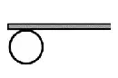
This beam support type only has vertical reaction, and allows horizontal movement and rotation
roller
pinned
fixed
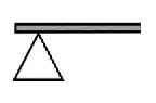
This beam support type has vertical and horizontal reaction, and allows rotation
roller
pinned
fixed
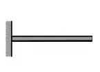
This beam support type has vertical, horizontal, and moment reaction
roller
pinned
fixed
Steel reinforcement is equal to concrete strength
balance
under reinforcement
over reinforcement
no reinforcement
Steel reinforcement is less than concrete strength.
balance
under reinforcement
over reinforcement
no reinforcement
Steel reinforcement is greater than concrete strength.
balance
under reinforcement
over reinforcement
no reinforcement
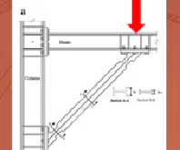
A bracing system where diagonal supports at right angles
Knee Bracing
Chevron Bracing
X-Bracing
Portal Bracing

A bracing system where V-shaped supports for lateral stability.
Knee Bracing
Chevron Bracing
X-Bracing
Portal Bracing
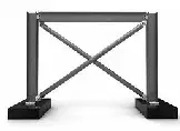
A bracing system where cross-shaped supports for rigidity.
Knee Bracing
Chevron Bracing
X-Bracing
Portal Bracing
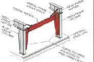
A bracing system of vertical and horizontal frame reinforcement.
Knee Bracing
Chevron Bracing
X-Bracing
Portal Bracing
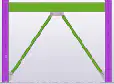
A bracing system where upside-down v-shaped supports for strength.
Knee Bracing
Inverted V-Bracing
Eccentric Bracing
Rigid Frame Bracing
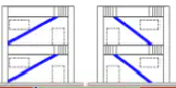
A bracing system of off-centre diagonal reinforcements.
Knee Bracing
Inverted V-Bracing
Eccentric Bracing
Rigid Frame Bracing

A bracing system of stiff, interconnected structural members.
Knee Bracing
Inverted V-Bracing
Eccentric Bracing
Rigid Frame Bracing
The minimum tread depth according to RA 9514
100 mm
180 mm
280 mm
300 mm
The maximum riser according to RA 9514
100 mm
180 mm
280 mm
300 mm
The minimum riser according to RA 9514
100 mm
180 mm
280 mm
300 mm
The maximum riser according to PD 1096
200 mm
250 mm
280 mm
300 mm
The minimum tread according to PD 1096
200 mm
250 mm
280 mm
300 mm

