
 Worksheets
Introduction to Engineering Drawings
Total questions: 20
Worksheet time: 10mins
Which pair best represents fundamental types of engineering drawings used to depict 3D forms and multiple views?
Orthographic and isometric views together
Freehand sketch and assembly outline
Detail sheet and cross-sectional cutaway
Sectional plan and exploded assembly
First-angle and third-angle projection
Which statement best defines a freehand sketch in engineering?
Drawn quickly using measuring instruments
Drawn without instruments, pencil and eraser only
Drawn digitally with precise CAD tools
Drawn with rulers to maintain exact scale
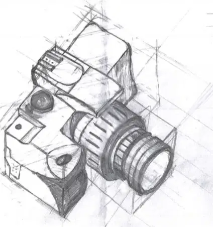
You must explain a product idea to both engineers and marketers during a meeting without CAD available. Which approach is most effective?
Describe the concept verbally for ten minutes
Prepare a detailed scaled engineering drawing
Create a freehand sketch to illustrate key features
Wait until measurement tools are available
Which statement best defines orthographic projection in engineering drawing?
Modeling a solid using parametric constraints
Rendering shaded pictorials for realistic appearance
Sketching perspective with vanishing points and depth
Projecting a single 3D view onto a flat surface
Why are multiple views typically used in an orthographic drawing of a component?
A single view rarely shows every important feature
Extra views reduce paper consumption and waste
Multiple views improve colour accuracy and shading
One view always distorts dimensions and scale
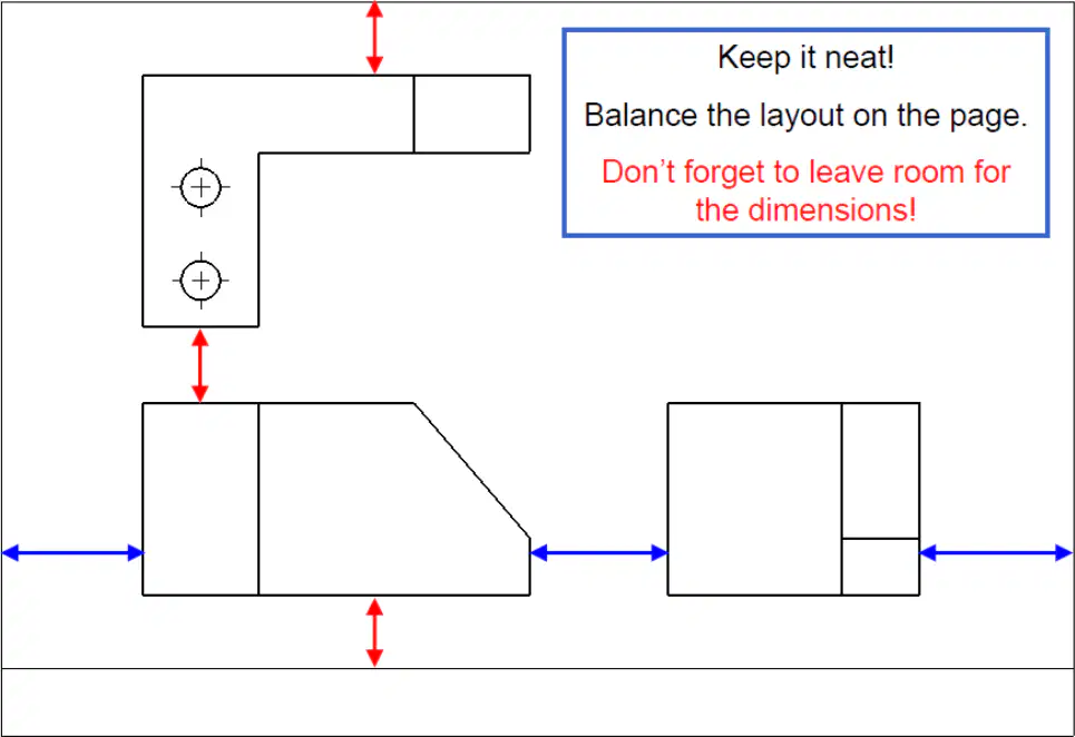
Refer to the layout diagram. Which placement principle helps maintain clarity when creating an orthographic projection?
Balance the layout and leave room for dimensions
Place views randomly to show different angles
Rotate each view to fit compactly in corners
Maximize drawing size to fill the entire sheet

Looking at the elements diagram, which view is adjacent directly above the front view in a standard orthographic arrangement?
Bottom view positioned above the front view
Back view centered above the front view
Right-side view aligned over the front view
Top view aligned over the front view
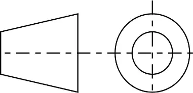
In the projection symbols shown, which side of the symbol depicts first angle projection?
Circle on left of cone
Circle above the cone
Cone below the circle
Cone on left of circle
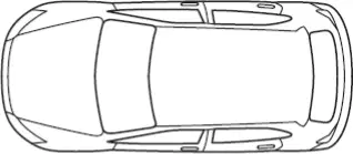
You are switching from first angle to third angle projection for the same car. Which change in view arrangement is correct?
Top view moves above front view
Top view moves below front view
Right side view moves to left of front
Left side view moves to left of front
In first angle projection, where is the model view placed relative to the face being viewed?
Rotated ninety degrees to the face
Above the viewing face in plan
Opposite to the face being viewed
On the same side as the face
Which BS 8888 symbol pair correctly represents third angle projection?
Cone right of circle symbol
Circle right of cone symbol
Square above triangle symbol
Triangle left of square symbol
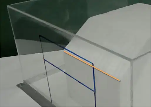
Using the glass box approach, which statement best describes how orthographic views are generated?
Scale dimensions uniformly on each face
Project perspective rays to a vanishing point
Rotate the object until edges align
Trace object outlines on the box faces
Which statement best defines an isometric drawing used in engineering design?
A perspective sketch with vanishing points
An orthographic plan showing front views
A 2D drawing that suggests a 3D view
A 3D model rendered from CAD software
In an isometric projection, what angle are the width and depth axes typically set relative to the horizontal?
15 degrees from the horizontal
60 degrees from the horizontal
30 degrees from the horizontal
45 degrees from the horizontal

Look at the L-shaped block diagram. Which use case correctly describes when isometric projections are most helpful?
As a visual aid for assembly diagrams
As precise dimensions for manufacturing
As formal tolerance specification sheets
As sole replacement for orthographic views
You are preparing a technical package for a machinist. Which combination of drawings provides both visual understanding and exact dimensions?
Exploded view without dimensions
Isometric projection alone without notes
Isometric projection with orthographic views
Freehand perspective sketch only
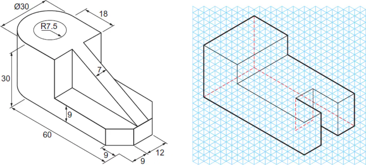
On the isometric part with dimensions shown, which statement explains the advantage of the isometric view over the dimension list?
It shows hidden interior features automatically
It replaces all detailed orthographic views
It guarantees precise manufacturing tolerances
It communicates overall 3D form clearly

An engineer suspects a hidden side hole on a part. Which drawing approach best ensures that such features are shown clearly for manufacturing?
Single isometric view of the part
Orthographic views from multiple sides
Exploded isometric with shading only
Freehand perspective sketch without dimensions

In a section view of a machined block, what convention indicates solid material that has been cut by the slicing plane?
Bold hidden-edge dashes
Thin phantom outlines
Parallel cross-hatching lines
Centerlines with dots

You need to reveal the internal shape of a component with a central hole. Which action produces the required section view?
Slice through the object
Increase isometric scale
Remove all outer edges
Rotate orthographic views

