
 Worksheets
Level 2 4510-206
Total questions: 28
Worksheet time: 14mins
Which statement best describes the characteristics of the headstock of a lathe?
It supports the free end of the workpiece and can move along the bed
It houses the spindle and drive mechanisms and provides speed control
It carries the cutting tool and moves it along and across the work
It is primarily a safety guard that encloses moving parts
Which statement best describes the characteristics of the knee of a milling machine?
It houses the spindle and speed change mechanisms
It provides vertical movement for the table and saddle and supports them
It is the base that carries the entire load of the machine
It is a safety enclosure around the rotating cutter
Which option best describes a difference between a 3‑jaw chuck and a 4‑jaw chuck, other than the number of jaws?
A 3‑jaw chuck typically self‑centers, while a 4‑jaw chuck allows independent jaw adjustment
Both are always self‑centering with the same accuracy
A 3‑jaw chuck is used only for square workpieces, while a 4‑jaw is only for round ones
A 4‑jaw chuck cannot hold work off‑center, while a 3‑jaw can
Select three workholding devices that are suitable for use on a milling machine.
Machine vise
V‑blocks with clamps
Lathe tailstock
Rotary table
Collet chuck for milling arbors
What is meant by the term rake angle when using a lathe?
The angle between the tool face and a line perpendicular to the work surface that influences chip flow
The angle of the tailstock offset used for taper turning
The angle between the spindle axis and the bed
The angle of the cross‑slide travel relative to the carriage
What is the primary purpose of a boring tool when used on a lathe?
To cut external threads inside a hole
To enlarge or finish the internal diameter of a hole to accurate size and finish
To drill an initial pilot hole
To face the end of a workpiece
What is the primary purpose of a tapping tool when used on a lathe?
To create internal threads in a pre‑drilled hole
To cut external threads on a shaft
To enlarge an existing bore for press‑fit
To produce a smooth external cylindrical surface
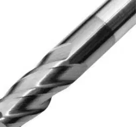
Identify the milling machine cutting tool shown in Figure 1.
End mill
Slot drill
Ball‑nose end mill
Twist drill

Identify the milling machine cutting tool shown in Figure 2.
Countersink
Ball‑nose end mill
Face mill
Center drill
Describe how a Vernier calliper is used to measure the length of a part.
Close the jaws lightly on the part, read the main scale and Vernier scale to obtain the measurement.
Tighten the locking screw to clamp the part and read only the Vernier scale.
Place the part between the depth rod and the beam and read the dial face.
Zero the calliper on a gauge block and then subtract the part’s thickness from the zero reading.
Describe how a dial test indicator is used.
Mount the indicator on a stand, contact the surface with the stylus, and observe needle deflection to detect runout or misalignment.
Clamp the indicator to the spindle and read the diameter directly from the dial.
Place the indicator between two parallels to measure mass by needle position.
Use the indicator as a height gauge by sliding it across a surface plate and reading absolute height.
One possible safety hazard when using machines is flying debris. Describe three other potential safety hazards when using a lathe or milling machine.
Entanglement with rotating parts such as chucks or cutters
Contact with sharp edges or hot chips
Electric shock from faulty wiring or damaged cables
Exposure to excessive noise leading to hearing damage
Eye strain from poor lighting
State two control measures that would reduce the risk of injury from flying debris when using a lathe or milling machine.
Wear appropriate eye protection such as safety goggles or a face shield
Use machine guards and close the chuck or splash guard during cutting
Increase spindle speed to shorten exposure time
Blow chips toward the operator to clear the work area
Describe what is meant by a counterbored hole.
A hole with a cylindrical enlarged recess to allow a bolt head or socket to sit below the surface
A conical hole that allows a flat-head screw to sit flush with the surface
A through‑hole that is tapped to accept a threaded fastener
A hole that does not break through the far surface
Describe what is meant by a countersunk hole.
A conical recess at the mouth of a hole to allow a flat‑head screw to sit flush
A cylindrical recess at the mouth of a hole to fit a hex socket head
A tapered hole that is threaded to accept a pipe fitting
A hole bored deeper than its diameter without any recess
Describe what is meant by a blind hole.
A hole that does not pass completely through the workpiece
A hole with a conical recess for a flat‑head screw
A hole with a cylindrical recess for a cap screw head
A hole that has been threaded after drilling
Describe what is meant by a ‘datum’.
A reference feature or point from which measurements are taken or to which part geometry is related
The final dimension specified on a drawing after tolerance is applied
A measuring tool used to check part diameter
A zero reading on a micrometer after calibration
Describe what is meant by ‘knurling’.
A process of impressing a patterned texture onto a cylindrical surface using a knurling tool
A method of cutting a keyway using a single‑point tool
A grinding operation to improve surface finish after turning
A heat‑treating process to harden the surface of a shaft
State three types of slot that can be produced on a milling machine.
T‑slot
Keyway slot
Dovetail slot
Rectangular/straight slot
Round-bottom groove made with a form tool
Describe how to align a workpiece on a milling machine.
Clamp the workpiece, use a dial test indicator along an edge to square it to the table or vise, and adjust until minimal runout is shown
Clamp the workpiece by eye parallel to the table and begin cutting slowly
Rotate the spindle by hand and listen for vibration to confirm alignment
Place the workpiece against any stop and tighten without measurement
Describe how a cutting tool is mounted on a lathe.
Secure the tool in the tool post with minimal overhang, set cutting edge on center height, and tighten all clamps firmly
Grip the tool in the drill chuck and hand‑tighten to avoid distortion
Hold the tool against the work with a magnetic base while starting the cut
Clamp the tool above center to increase rake and leave long overhang for flexibility
Explain how the turning speed changes when the diameter of the workpiece changes.
For a constant cutting speed, spindle speed is inversely proportional to diameter; larger diameter requires lower rpm
For a constant cutting speed, spindle speed is directly proportional to diameter; larger diameter requires higher rpm
Spindle speed is independent of diameter for all materials
Diameter only affects feed rate, not spindle speed
Explain why the process parameters are different when milling brass and mild steel.
Brass has higher machinability and lower cutting forces than mild steel, allowing higher cutting speeds and lighter feeds for similar surface finish
Brass is harder and tougher than mild steel, so it always requires slower speeds and heavier feeds
Both materials have identical thermal properties, so parameters should be the same
Differences are due only to tool geometry, not material properties
Describe the difference between a symptom and a cause of a defect in a machined product. (2 marks)
A symptom is the visible or measurable manifestation of a defect; a cause is the underlying factor that created it.
A symptom is the root reason for a defect; a cause is the superficial observation.
A symptom is the machine setting; a cause is the inspection method.
A symptom and a cause are the same and interchangeable.
Describe two methods of monitoring machine performance. (4 marks)
Vibration monitoring with sensors to track bearing and spindle health.
Lubricant condition analysis to detect wear or contamination.
Changing paint color of the machine enclosure.
Adjusting operator shift schedules.
State two documents that contain engineering information that products are typically evaluated against. (2 marks)
Engineering drawings with dimensions and tolerances.
Product specifications or technical standards.
Purchase orders from customers.
Marketing brochures.
Describe three quality criteria that a turned product should be evaluated against. (6 marks)
Dimensional accuracy against tolerance (e.g., diameter, length).
Surface finish or roughness on turned surfaces.
Concentricity/runout of cylindrical features.
Exterior paint color of the part.
State two applications of visual inspection. (2 marks)
Detecting surface defects such as scratches, burrs, or cracks.
Verifying assembly completeness and correct orientation of parts.
Measuring internal hardness without equipment.
Adjusting CNC tool offsets during machining.

