
Font size
 Worksheets
Transformers Multiple-Choice Worksheet
Total questions: 161
Worksheet time: 1hrs 21mins
A certain transformer has 400 turns in the primary winding and 2,000 turns in the secondary winding. The turns ratio is:
0.2
0.4
5
25
The primary winding of a transformer has 110 V ac. What is the secondary voltage if the turns ratio is 1/5?
550V
10V
220V
110V
A transformer
Changes AC to DC
Changes DC to AC
Steps up or down DC voltage.
Steps up or down AC voltage
Which of the following does not change when a transformer is working?
Current.
Voltage.
Frequency.
All of the above.
What is the working principle of a single phase transformer?
Faraday’s law.
Lenz’s law.
Archimedes's law.
Einstein’s law.
What does EMF stand for?
Electro-motive force.
Engine-motor frequency.
Electro-motor force.
Engine-motive force.
The unit of measurement of transformer capacity is
VA or KVA
W OR KW
both a and b right
both a and b wrong
Material used for construction of transformer core is:
Wood.
Copper.
Aluminium.
Silicon steel
In transformer the energy is conveyed from primary to secondary
Through to secondary.
Through air.
By the flux
None of the above.
An ideal transformer has 750 turns on the primary coil and 50 turns on the secondary coil. The current in the secondary coil is 3 A and the primary voltage is 30 V. The secondary voltage is
2V
3V
20V
15V
An ideal transformer has 750 turns on the primary coil and 50 turns on the secondary coil. The current in the secondary coil is 3 A and the primary voltage is 30 V. The current flowing through the primary coil
0.1A
0.2A
0.4A
0.3A
The voltage transformation ratio of a transformer is equal to the ratio of
primary turns to secondary turns
secondary current to primary current
secondary induced e.m.f. to primary induced e.m.f.
secondary terminal voltage to primary applied voltage
The maximum load that a power transformer can carry is limited by its
temperature rise
dielectric strength of oil
voltage ratio
copper loss
If a transformer is continuously operated the maximum temperature rise will occur in
core
windings
tank
any of the above
Losses which occur in rotating electric machines and do not occur in transformers are
friction and windage losses
magnetic losses
hysteresis and eddy current losses
copper losses
For given applied voltage, with the increase in frequency of the applied voltage
eddy current loss will decrease
eddy current loss will increase
eddy current loss will remain unchanged
none of the above
The size of a transformer core will depend on
frequency
area of the core
flux density of the core material
(A) and (B) both
The transformer oil should have _____ volatility and _____ viscosity.
low, low
high, high
low, high
high, low
For the parallel operation of single phase transformers it is necessary that they should have
same efficiency
same polarity
same kVA rating
same number of turns on the secondary side
If the supply frequency to the transformer is increased, the iron loss will
not change
decrease
increase
any of the above
The magnetising current of a transformer is usually small because it has
small air gap
large leakage flux
laminated silicon steel core
fewer rotating parts
Delta/star transformer works satisfactorily when
load is balanced only
load is unbalanced only
on balanced as well as unbalanced loads
none of the above
Star/star transformers work satisfactorily when
load is unbalanced only
load is balanced only
on balanced as well as unbalanced loads
none of the above
In a transformer the resistance between its primary and secondary is
zero
1 ohm
1000 ohms
infinite
The thickness of laminations used in a transformer is usually
0.4 mm to 0.5 mm
4 mm to 5 mm
14 mm to 15 mm
25 mm to 40 mm
The purpose of providing iron core in a step-up transformer is
to provide coupling between primary and secondary
to increase the magnitude of mutual flux
to decrease the magnitude of magnetizing current
to provide all above features
The maximum efficiency of a distribution transformer is
at no load
at 50% full load
at 80% full load
at full load
Power transformers are designed to have maximum efficiency at
nearly full load
70% full load
50% full load
no load
The primary winding of a transformer has a 120 V ac supply. What is the value of secondary voltage if the turn ratio is 10?
120 V
12 V
12000 V
1200 V
If the supply frequency (f) of a transformer decreases, the effect of frequency on the transformer's secondary output voltage?
Remain the same
Decreases
Increases
All of these
Transformer core are laminated in order to
Reduce copper loss
Minimize eddy current loss
Reduce eddy current and hysteresis loss
Reduce hysteresis loss
The short circuit test in the transformer is performed on
High voltage side
light voltage side
Both
Either option A or B.
The secondary voltage is 440 Volt, and primary voltage is 220 Volt, then a comparison of the secondary coil and primary coil is
4/1
5/2
2/1
7/5
The transformer ratings are expressed in terms of
KW (Kilo-Watt)
Volts
KVAR (Kilo-Volt-Ampere-Reactive)
KVA (Kilo-Volt-Ampere)
Oil is provided in an oil-filled transformer for
Lubrication
Cooling
Insulation
Both cooling and Insulation
The efficiency of a transformer is maximum when
Eddy current loss = iron loss
Hysteresis loss = copper loss
Eddy current loss = hysteresis loss
Iron loss = copper loss
Which winding in a transformer has a greater number of turns
Constant voltage winding
Low voltage winding
Secondary winding
High voltage winding
The necessary condition for the parallel operation of two single-phase transformers is that they must have the same
Turn ratio
Polarity
KVA rating
Both option A & B
In an autotransformer, the primary and secondary are ....... coupled.
Magnetically coupled
Electrically coupled
Both magnetically and electrically coupled
None of these
The maximum load that a power transformer can carry is limited by its
Voltage ratio
Dielectric strength of the coil
Copper loss
Temperature rise
In an induction motor, if the air gap is increased
Its speed will reduce
Its efficiency will improve
Its power factor will reduce
Its breakdown torque will reduce
An induction motor works with
DC only
AC only
Both AC & DC
None of these
The stator frame in an induction motor is used to
Hold the armature stampings in position
Ventilate the armature
Protect the whole machine
Provide return path for the flux
The stator core of a 3-phase induction motor is laminated in order to reduce the
Eddy current loss
Hysteresis loss
Both eddy current and hysteresis loss
Weight of the stator
If all the stator coils of an induction motor are connected for the same magnetic polarity, there will be formed an equal number of
Rotor poles with same polarity
Rotor poles with opposite polarity
Consequent poles with opposite polarity
Consequent poles with same polarity
The induction motor shaft should be
Hollow
Stiff
Flexible
Any of these
The induction motor is made of
Mild steel
Cast iron
High speed steel
Stainless steel
In a 3-phase squirrel cage induction motor
Rotor conductors are short circuited through end rings
Rotor conductor ends are short circuited through slip rings
Rotor conductors are kept open
None of the above
The squirrel cage rotor of a 6-pole induction motor can be used for ____ induction motor
Only 6-pole
6 or 12 poles
Any number of poles in an induction motor
None of the above
The squirrel cage induction motors are provided with blades in order to
Facilitate cooling of rotor
Balance the rotor dynamically
Eliminate noise
None of these
The rotor of a 3-phase wound rotor induction motor is provided with
Single phase winding
Three phase winding
Heavy copper or aluminum bars placed in rotor slots
Heavy short-circuited end rings
In a 3-phase slip ring induction motor, the rotor winding terminals are brought out through slip rings to
Connect extra resistance across them during starting
Connect them either in star or in delta as per need
Connect to 3-phase AC supply
Close the rotor circuit externally
The rotor winding for a 3-phase slip ring induction motor having delta connected stator must be connected in
Delta
Star
Delta or star according to need
None of the above
In a 3-phase slip ring induction motor, brushes are connected to
External star connected resistors
DC supply
3-phase AC supply
Equalizing coils
At s=0 the torque of an induction motor is
0
Equal to full load
Very high
Nearly zero
A 3 phase slip ring induction motor has
Short circuit rotor
Wound rotor
Double cage rotor
All of the above
Copper loss in rotor of a induction motor
Is lost in friction
Is lost in windage
Appears as noise
Appears as heat
The difference between the synchronous speed and the actual speed of an induction motor is known as
Lag
Slip
Back lash
Regulation
An induction motor works with
DC only
AC only
Both AC and DC
None of them
As the load on an induction motor increases
Its power factor goes on increasing up to full load then it falls again
Its power factor goes on increasing
Its power factor goes on decreasing
Its power factor remains unchanged
In a squirrel cage induction motor, the starting current is
Half the rated current
Equal to the rated current
2 to 3 times the rated current
5 to 7 times the rated current
A 3 phase induction motor takes a line current of 30A when started by direct switching. If a star-delta starter is used, the line current would be
10 A
5 A
30 A
17.32 A
Direct on line starting current as compared with star-delta starting current is approximately
5 times
4 times
3 times
2 times
For induction motors, normally
The stator winding is connected to supply and the rotor winding is open circuited
Both the stator and the rotor winding are connected to supply
The stator winding is connected to supply and the rotor winding is short circuited
The rotor winding is connected to supply and the stator winding is short circuited
A wound rotor induction motor can be distinguished from squirrel cage induction motor by
Presence of slip rings
Diameter of shaft
Direction of rotation
Size of frame
As the load on induction motor goes on increasing
Power factor remains practically unchanged
Power factor goes on increasing up to rated load then it starts falling
Power factor goes on increasing even beyond full load
Power factor goes on decreasing
Full load current of a 20kW , 3 phase, 50Hz , 440V induction motor is
78 A
48 A
38 A
10 A
A two-pole induction motor has a synchronous speed of 3600rpm . The frequency of supply to the stator is
60 Hz
50 Hz
40 Hz
36 Hz
Two induction motors A and B have no load operating power factor of 0.15 and 0.25 respectively. It can be concluded that
Motor B will have more windage losses as compared to motor A
Motor A will have more windage losses as compared to motor B
Motor B will be bigger in size as compared to motor A
Motor A will be bigger in size as compared to motor B
If a squirrel cage induction motor runs hot the possible cause could be
Over load
Uneven airgap
Low supply frequency
Any of the above
In case of slip ring induction motors, the starting torque can be increased by
adding external resistance and inductance to the rotor
adding external resistance to the rotor
adding external inductance to the rotor
adding external capacitance to the motor
In case the air gap in an induction motor is increased
power factor will increase
the magnetizing current of the rotor will decrease
the magnetizing current of the rotor will increase
noise will increase
Various methods for starting a 3-phase induction motor are given. Which method will require six stator terminals?
DOL
Auto transformer
Rheostat
Star-delta
If an induction machine is run at above synchronous speed, it acts as
a synchronous motor
an induction generator
an induction motor
none of the above
A 60 HP, 440 V, 50 Hz, 3-phase 6 pole, induction motor runs at 960 rpm at full load. The slip s and frequency of rotor f are
s = 2.5, f = 125
s = 4.0, f = 2.0
s = 4.0, f = 2.5
s = 4.0, f = 20
A 4-pole, 3-phase, 400 V, induction motor runs at 480 rpm when the slip is 4%. Supply frequency must be
100 Hz
50 Hz
25 Hz
16 2/3 Hz
When the supply to an induction motor is switched on, in the beginning, the induced emf in the rotor will be
zero
minimum
maximum
same as during running
A 3-phase induction motor has a copper loss of 80 watts and slips of 4%. The rotor input must be
8 kW
4 kW
2 kW
0.2 kW
A slip ring induction motor is preferred to squirrel cage induction motor when
fluctuating loads are anticipated
frequent starting is necessary
low starting torque is desired
high starting torque is desired
For a squirrel cage induction motor running on no load
rotor induced emf is very small
slip is very large
rotor current is large
power factor is large
Generally, in alternator divided winding rotor is preferred to a conventional winding rotor, because it gives
Better damping
Less harmonics
More efficiency
None of these
For a two pole, 50 Hz, 3 phase synchronous motor the speed of rotating magnetic field is
1000 rpm
2000 rpm
3000 rpm
3500 rpm
The open circuit voltage and short circuit current of a 3 phase, star connected alternator are 1050 V and 250 A respectively. Its field current is 12 A. Then the synchronous impedance of alternator will be
1.34 ohm
1.69 ohm
2.42 ohm
2.85 ohm
Which type of rotor is generally used for high speed alternators or turbo alternators?
Salient pole type
Projected pole type
Smooth cylindrical type
Both (A) & (B)
If the field of the synchronous motor is overexcited then its power factor will be
Lagging
Leading
Unity
Zero
To have effective synchronization without any interruption, the necessary conditions which must be satisfied are
The terminal voltage and frequency of the incoming machine must be same as that of bus bar voltage and frequency
With respect to the external load, the phase of alternator voltage must be identical with that of the bus bar voltage
Both (A) and (B)
None of these
Back emf in case of synchronous motor depends on the
Excitation given to the field winding
Speed
Both (A) and (B)
None of the above
If two mechanically coupled alternators deliver power at 50 Hz and 60 Hz respectively, then the highest speed of alternators will be
1200 rpm
1500 rpm
600 rpm
300 rpm
The synchronous motor as a synchronous condenser is used to
Improve power factor
Reduce hunting
Both (A) and (B)
None of these
An over excited synchronous motor operating on no load condition is called as
Synchronous capacitor
Synchronous condenser
Both (A) and (B)
None of these
When the excitation of a synchronous motor is changed keeping the load constant then the
Power factor will change
I, cos φ remains constant
Both (a) and (b)
None of these
In a synchronous motor the torque produced will be maximum when load angle is equal to
0° electrical
90° electrical
180° electrical
360° electrical
If the load on a synchronous motor increases then its
Current drawn by motor increases and load angle decreases
Current drawn by motor decreases and load angle remains constant
Current drawn by motor remains constant and load angle increases
Current drawn by motor increases and load angle also increases
With increase in load, the speed of synchronous motor
Increases
Decreases
Remains constant
None of the above
A synchronous motor is started by using damper winding. When the motor runs at synchronous speed then the induced emf in the damper winding will be
Zero
Maximum
Half of the terminal voltage
None of these
The method used for starting synchronous motor is/are
Using pony motors
Using damper windings
As a slip ring induction motor
All of the above
Synchronous motors are
Self starting
Not self starting
Both (A) and (B)
None of these
Synchronous motor works on the principle of
Mutual induction
Electromagnetic induction
Magnetic locking
None of these
A synchronous motor draws 2 MVA at a power factor of 0.8 leading. If the efficiency developed in the motor is 90% then the power developed is equal to
1212 kW
1440 kW
1676 kW
1767 kW
The increase in mechanical torque in case of alternator will
Increase the armature current and reduce the power factor
Increase the armature current and improve the power factor
Decrease the armature current and improve the power factor
Decrease the armature current and reduce the power factor
The change in excitation of the two alternators operating in parallel causes
Only the kVAR sharing of two alternators without disturbing kW sharing of the two machines
Only the kW sharing of two alternators without disturbing kVAR sharing of the two machines
Both the kVAR sharing and kW sharing of two alternators
None of the above
If a 3 phase alternator is short circuited at its terminal, then the initial value of short circuit current will be limited by
Synchronous reactance
Transient reactance
Sub transient reactance
All of the above
In a salient pole synchronous generator direct axis reactance is
Greater than quadrature axis reactance
Less than quadrature axis reactance
Equal to quadrature axis reactance
None of the above
The direct axis reactance Xd and quadrature axis reactance Xq obtained from slip test are
Xd = minimum voltage/minimum current, Xq = maximum voltage/maximum current
Xd = minimum voltage/maximum current, Xq = maximum voltage/maximum current
Xd = maximum voltage/minimum current, Xq = minimum voltage/maximum current
Xd = maximum voltage/maximum current, Xq = minimum voltage/minimum current
The synchronous generator supplies leading power factor and lagging power factor respectively when it is
Over excited, under excited
Over excited, over excited
Under excited, under excited
Under excited, over excited
The electrical power output of an alternator will be maximum, if the power angle is equal to
0∘
45∘
90∘
180∘
The synchronous generator is loaded for obtaining zero power factor characteristics by using
D.C. motor
Lamp load
Synchronous motor
All of these
An ideal synchronous motor has no starting torque because the
Rotor is made up of salient poles
Relative velocity between the stator and the rotor mmfs is zero
Relative velocity between the stator and rotor mmfs is not zero
Rotor winding is highly reactive
In a synchronous motor
The rotor mmf and stator mmf are stationary with respect to each other
Rotor mmf rotates slightly faster in comparison to stator mmf
Stator mmf rotates slightly faster than rotor mmf
None of the above
A synchronous machine is of revolving armature and stationary field type. Under steady running condition the air-gap field
Rotates at synchronous speed with respect to stator
Rotates at synchronous speed in the direction of rotation of rotor
Remains stationary with respect to stator
Remains stationary with respect to rotor
In a synchronous machine, if the armature field axis is ahead of the field flux axis in the direction of rotation, the machine is operating as a
Synchronous motor
Synchronous generator
Asynchronous motor
Asynchronous generator
In a 3‑phase synchronous motor
Remains constant at all loads
Varies with load
Varies with speed
Varies with power factor
In a 3‑phase synchronous motor, the armature mmf leads the air‑gap flux and the air‑gap flux leads the field mmf
The filed mmf leads the air gap flux leads the armature mmf
The armature mmf leads the air gpap flux and air gap flux leads the field mmf
The armature mmf leads the air gap flux and air gap flux lags behind the field mmf
None of the above
The relative speed between the magnetic fields of stator and rotor under steady‑state operation is zero for
A d.c. machine
An induction machine
A synchronous machine
All of the above
A 3‑phase synchronous motor has
High starting torque
No starting torque
Low starting current
Low starting torque
A 10 ‑pole, 25Hz alternator is directly coupled to and is driven by a 60Hz synchronous motor. What is the number of poles for the synchronous motor?
48
12
24
16
A 3‑phase synchronous motor needs dc supply for excitation
Continuously
At the starting instant only
Of stator
None of these
The armature current of a synchronous motor on no load
Leads the applied voltage by 90∘
Lags behind the applied voltage by 90∘
Is in phase with the applied voltage
Is zero
As the load is increased on a synchronous motor, its speed
Decreases
Increases
Remains constant and additional load is supplied by shift in relative position of the rotor with respect to the stator rotating magnetic field
Remains constant for some time and then falls abruptly
The synchronous motor meets an increase in load by taking more armature current because
The rotor pole falls back relative to the stator pole causing an increase in motor current
The back emf decreases causing an increase in motor current
The rotating field is strengthened causing an increase in motor current
None of the above
In a d.c. machine, the form of armature reaction mmf is
Triangular
Sinusoidal
Saw‑tooth
Rectangular
For a low‑reluctance path for the flux in an armature, the permeability of the material should be
High
Low
Both (A) and (B)
None of these
In a D.C. machine, the form of armature reaction mmf is
Triangular
Sinusoidal
Saw‑tooth
Rectangular
If A is the number of parallel paths and P is the number of poles, then the number of parallel paths in lap winding and in wave winding is
A=P , A=2P
A=2P , A=P
A=2 , A=P
A=P , A=2
In a self‑excited generator, if the series field opposes the shunt field, then the generator is
Cumulatively compounded
Differentially compounded
Series generator
None of these
Laminations or stampings are used to reduce eddy‑current losses. The orientation of laminations should be such that
They are perpendicular to the paths of eddy current and flux both
They are parallel to the paths of eddy current and flux both
They are perpendicular to the paths of eddy current and parallel to the flux
They are parallel to the path of eddy current and perpendicular to the flux
With the increase in temperature, the speed of series and shunt motor will respectively
Increase, decrease
Decrease, increase
Increase, increase
Decrease, decrease
If Eb is the back emf of a d.c. motor and V is the terminal voltage, then the condition for maximum power is
Eb=V
Eb=2V
Eb=2V
Eb=V2
The armature reaction in a d.c. machine causes distortion in the main field flux. This effect of armature reaction can be reduced by
Increasing the length of air‑gap
Decreasing the length of air‑gap
Increasing the number of poles
Decreasing the number of poles
D.C. shunt motors are commonly used in
Cranes
Electric traction
Elevators
Lathe machines
The brush contact losses in a d.c. machine are
Inversely proportional to the square of current
Directly proportional to the square of current
Inversely proportional to the current
Directly proportional to the current
When a d.c. motor runs on no load, then
Back emf is almost equal to applied voltage
Back emf will be greater than applied voltage
Back emf will be less than applied voltage
None of these
If the number of conductors and the speed of a lap‑wound generator are both doubled, then the generated emf will be
Remain the same
Twice the former
Four times the former
Half of the former
If a shunt motor is started with its field winding open, then
It will rotate at the same speed as with its field winding closed
It will rotate at less speed than with its field winding closed
It will rotate at dangerously high speed
None of these
Electrical power output in a d.c. generator is equal to
Electrical power developed in armature - copper losses
Mechanical power input - iron and friction losses
Electrical power developed in armature - iron and copper losses
Mechanical power input -iron and friction losses - copper losses
Differential compound motors are mainly used in
Drilling machines
Elevators
Electric traction
Not suitable for any practical application
Which motor is not suitable for the application of centrifugal pumps?
series motor
shunt motor
Cumulatively compounded motor
Differential compound motor
The speed of permanent magnet d.c. motor cannot be controlled by
Flux control method
Rheostatic control method
Electronic circuits
None of these
If a resistance is added in series with the field winding of a d.c. shunt motor, then its
Both speed and torque decreases
Both speed and torque increases
Speed decreases, torque increases
Speed increases, torque decreases
Which method is suitable for the speed control below and above the normal rated speed of a d.c. shunt motor?
Flux control method
Rheostatic control method
Voltage control method
All of these
In armature voltage control (rheostatic control) for speed control in a d.c. shunt motor, a variable resistance is
Added in series with the armature
Added in series with the field
Connected across armature
Both in series with armature and field
In the flux control method for controlling the speed of a d.c. shunt motor, the speed control is not possible
Below normal rated speed
Above normal rated speed
Both (A) and (B)
None of these
A series-wound motor is also called a universal motor because
It will run equally well using either an ac or a dc voltage source
It will run well below and above rated speed
It can be used in all kinds of applications
None of these
Speed of d.c. shunt motors are controlled by
Flux control method
Rheostatic control method
Voltage control method
All of these
In electric traction, which type of motor is generally used?
Shunt motor
Series motor
Cumulative compound motor
Differential compound motor
In a differential compound d.c. motor, with increase in load, speed
Increases
Decreases
Remains same
None of these
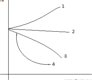
The speed–current characteristics are shown in the figure. Identify the different curves: 1, 2, 3, and 4.
1 – series, 2 – shunt, 3 – cumulative compound, 4 – differential compound
1 – cumulative compound, 2 – differential compound, 3 – series, 4 – shunt
1 – cumulative compound, 2 – differential compound, 3 – shunt, 4 – series
1 – differential compound, 2 – shunt, 3 – cumulative compound, 4 – series
If a d.c. series motor is started on very light load or on no load then
It will run at dangerously high speed which may damage the motor mechanically
It will run at very low speed
Load does not affect the speed of a d.c. series motor
None of these
The speed–armature current characteristics of a d.c. series motor is
Rectangular hyperbola
Linear
Parabolic
Parabolic till saturation and then linear
The speed of a d.c. series motor is
Directly proportional to both armature current and torque developed
Inversely proportional to the armature current and square root of torque developed
Directly proportional to the square of the armature current and square root of torque developed
Inversely proportional to the square of the armature current and square of torque developed
The starting torque developed in the d.c. series motor and in d.c. shunt motor is
High, low
High, moderate
Moderate, low
Moderate, high
Keeping the field excitation constant, the constant of proportionality between back emf and armature speed of d.c. motor is
Twice of the proportionality constant between developed torque and armature current
Half of the proportionality constant between developed torque and armature current
Same as that of proportionality constant between developed torque and armature current
None of these
As the load on d.c. motor increases, the current drawn by motor
Increases
Decreases
Remains same
None of these
A 220 V, d.c. motor draws an armature current of 20 A. Its armature resistance is 0.6 ohm. Then the induced emf in the motor will be
195 V
202 V
208 V
215 V
The compensating windings are used to neutralize the armature reaction in d.c. machines. These windings are connected
Across armature
In series with armature
Both (A) and (B)
None of these
In a D.C. machine, the commutator provides
Half wave rectification
Full wave rectification
Semi controlled rectification
Uncontrolled rectification
The armature in d.c. machines are always placed on rotor
Otherwise commutation will not be possible
Otherwise there will not be any induced emf
Otherwise current will not flow
All of these
In a d.c. machine, the eddy current losses mainly occurs in
Armature
windings
Yoke
At brush contact
For the construction of the armature of a d.c. machine, the best suited material is
cast iron
Silicon steel
Carbon
All of these
For the construction of the armature of a d.c. machine, the best suited material is
cast iron
Silicon steel
Carbon
All of these
If the armature current of dc series motor has become twice then the torque will become
Twice of the former
Four times of the former
One fourth of the former
Remains same

