
 Worksheets
Unit 216: Boilers Part 2 Combination boilers
Total questions: 25
Worksheet time: 13mins
Which statement best describes how a combination boiler supplies domestic hot water (DHW)?
Rainwater is collected and heated in an external tank
Cold water is heated by an open-vented cast coil
Pre-heated water is stored in a large DHW cylinder
Cold mains water is heated through a plate heat exchanger
Before installing a combination boiler, what should be checked at the property?
Incoming mains pressure and flow rates
Window glazing thickness and seals
Attic insulation depth and R-value
Boiler flue colour and wall paint
Which traditional components are NOT required with a combination boiler?
Sealed system expansion vessel
Cold water storage cistern
Feed and expansion cistern
Open-vented header tank
Domestic hot water cylinder
A sealed central heating system in a combi boiler primarily means
The DHW uses stored water open to air
The boiler has a sealed combustion chamber only
The heating circuit is pressurised and not open to atmosphere
The system automatically vents through roof pipes
Which limitation should be explained to customers about DHW draw-off with combi boilers?
Only one draw-off point should be used at a time
Two taps can run if boiler is set to eco
Multiple showers can run without temperature drop
Unlimited outlets can open at constant temperature
When a combi boiler is providing DHW, what usually happens to the central heating (CH) circuit?
The CH circuit is temporarily cut off
The CH circuit increases pump speed
The CH circuit runs at reduced temperature
The CH circuit continues unaffected
Why can it take time for DHW to reach temperature at a tap with combi boilers?
The loft tank slowly refills before heating
The pump circulates cold water for storage
The cylinder reheats after each use cycle
Water must travel and be heated on demand
In hard water areas, what issue can affect combi boiler performance?
Freezing in the open vent pipe
Corrosion in the loft cold tank
Scaling in the plate heat exchanger
Air ingress via the header tank
Flow rates for DHW in combi boilers are typically
Unlimited when mains pressure is high
Set by manufacturer to achieve a temperature rise
Completely user-adjusted with no limits
Dependent only on pipe size to taps
If the mains water supply is cut off, a typical combi boiler will
Use roof tank to maintain DHW
Switch to stored cylinder operation
Boil CH water to supply taps
Provide no DHW back-up supply
Match each combi boiler internal component to its function.
Diverter valve
Directs flow between DHW and CH circuits
Secondary DHW plate heat exchanger
Transfers heat to mains water for hot taps
Circulating pump
Moves water around central heating loop
Pressure relief valve
Safeguards by relieving excess pressure
PCB control board
Controls and coordinates electronic functions
Which requirement most influences whether a combi boiler can deliver adequate hot water to a large bath quickly?
Sufficient mains pressure and flow rate
Length of radiator pipework
Size of open-vented storage tank
Presence of gravity hot water loop
Which connection is used to fill a sealed combination boiler system?
A filling loop between CWS and CH return
A vent pipe from CH flow to cistern
An open header tank above the boiler
A drain cock on the heating circuit only
In normal operation, a combination boiler’s primary circuit is considered:
Sealed and pressurised circuit
Open and vented circuit
Gravity-fed low pressure
Partly sealed with open vent
Match each item with its role when filling a combination boiler.
Filling loop
Temporary bridge to pressurise system
CWS connection
Supplies cold water to the loop
CH return connection
Receives water back into the circuit
Vented header tank
Not used in sealed systems
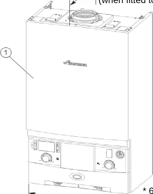
What is the overall width of the wall-hung boiler case shown?
390 mm
280 mm
690 mm
325 mm
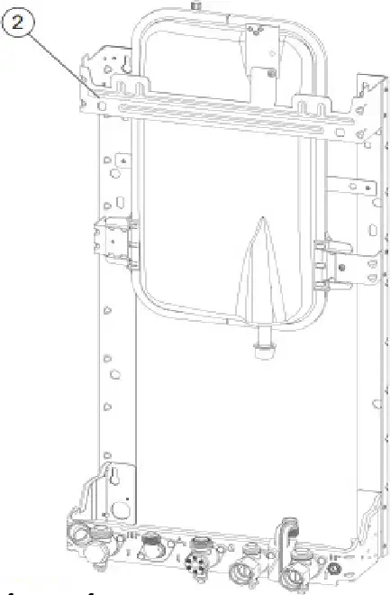
When fitted to the wall frame, what is the depth from the case front to the wall?
195 mm
690 mm
390 mm
280 mm
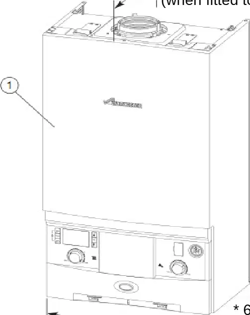
The height from the bottom to the top of the boiler case front is closest to which dimension?
325 mm
260 mm
690 mm
390 mm
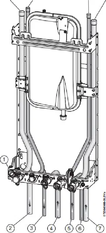
Match each connection on the combination boiler to its distance from the left case edge.
Condensate drain
33 mm
CH flow
65 mm
DHW outlet
130 mm
Gas
195 mm
CH return
325 mm
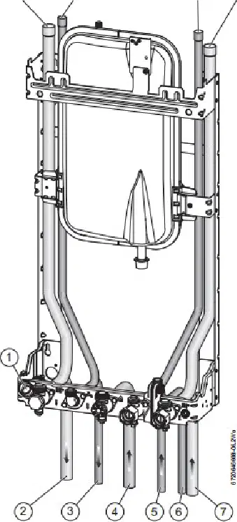
Which connection uses a 22 mm pipe diameter?
DHW outlet
CH flow
PRV drain
Gas
DCW mains in
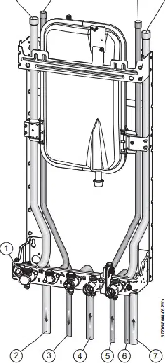
From the left case edge, which pair correctly orders the CH flow and gas connections?
195 mm then 65 mm
33 mm then 325 mm
65 mm then 195 mm
130 mm then 260 mm
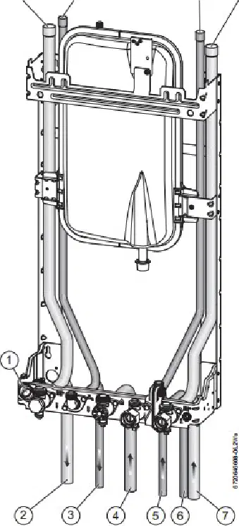
Which connection is located furthest to the right on the connection bar?
CH return at 325 mm
Gas at 195 mm
DCW mains in at 260 mm
PRV drain at 291 mm
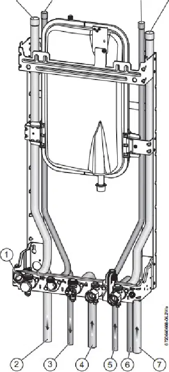
Select all connections that are specified at 15 mm diameter.
DCW mains in
DHW outlet
CH return
Condensate drain
PRV drain
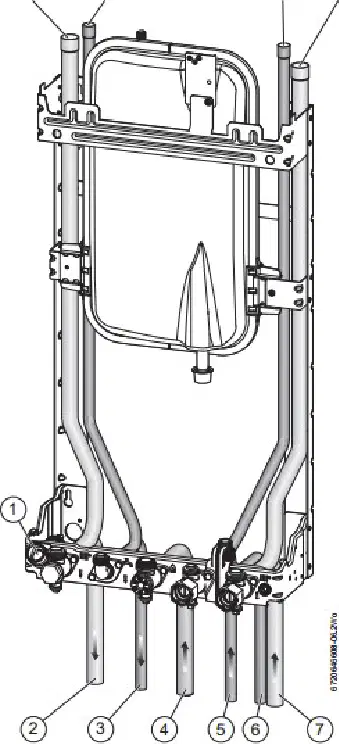
Which statement best describes the relative positions of the condensate and PRV drains?
Condensate is left of PRV drain
Condensate is right of PRV drain
Both share the same position
PRV drain is above condensate
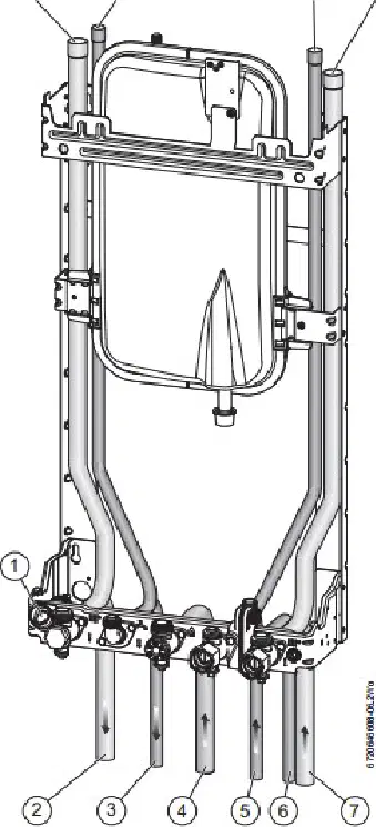
What is the correct pipe size for the CH return connection on this boiler?
18 mm
22 mm
15 mm
28 mm

