
 Worksheets
POB1-Information Used in the Workplace-Working Drawings
Total questions: 13
Worksheet time: 7mins
1:1 , 1:200, 1: 10, 1:50 are examples of:
Scales used in drawings
Ratio of cement to aggregates
Gradient of a ladder
A setting out rod will have a scale of:
1:1
1:10
1:50

True or False: A full size setting out rod is typically used by bench joiners to mark out joinery components.
True
False

1:5, 1:10, 1:20 are scales used for:
Setting our rods
Assembly Drawings
Block Plans

True or False: Assembly drawings provide detailed sections of how components fit together, such as the joint between two walls where they meet at a corner.
True
False
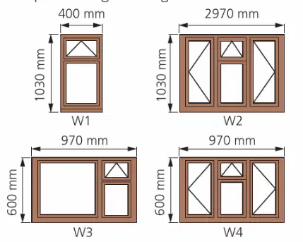
1:1, 1:2, 1:5, 1:10 are scales used for:
Setting out rods
Block Plans
Assembly drawings
Component range drawings
True or False: A component range drawing illustrates a full range of a particular component. For example, a ‘Window component range drawing’ would show views of every window for a particular building and their dimensions, and the positions of any openings.
True
False
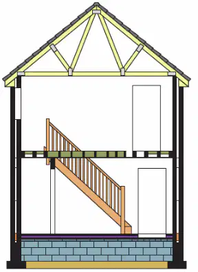
This drawing uses these scaled : 1:10, 1:20, 1:50. This drawing illustrates various views through a building or structure. They are used to see how different elements fit together in relation to the whole job. A section through a building might illustrate the depth of the foundation, the heights of the windows and the pitch of a roof. This type of drawing is called a :
Section drawing
Component range drawing
Setting out rod
Elevation drawing
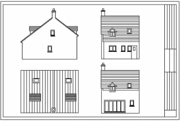
These drawings use the following scales: 1:10, 1:20, 1:50. These types of drawings show the views of a building from every angle. They provide a true representation of a building by illustrating the positions of the doors, windows and roof shape.
Elevation drawings
Sectional drawings
Block plan
Setting out rod
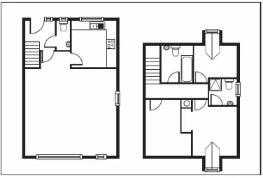
These types of drawings use the following scales: 1:50, 1:100, 1:200. They show the arrangement of the walls to form rooms on each level of a building. They also illustrate the positions of doors, windows, stairs, kitchens, bathrooms and so on. Carpenters may refer to these drawings when they are hanging doors, so that they know which way they swing.
Floor plans
Block plans
Setting out rod
Elevation drawings

This drawing uses these scales: 1:200, 1:500. This type of drawing offers a bird’s eye view of the building plot, or multiple plots on bigger construction sites. They illustrate the boundary (perimeter) of the site, roads, parking, footpaths, waterways and existing trees.
Site plan
Block plan
Assembly drawing
Component range drawing

Site plans show services, also referred to as ‘utilities’, such as: l l l electrical cables l gas l communication (telephone, internet and cable television connections).
mains water pipes
drains
electrical cables
gas
communication (telephone, internet and cable television connections)
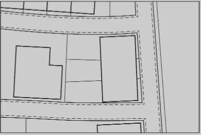
These drawings use the following scales: 1:1250, 1:2500.
These drawings are usually produced to illustrate a building plot in relation to the surrounding area. These drawings are used by the client when submitting plans for approval to the local authority’s planning department. These drawings are called:
Site plans
Block plans
Sectional drawings
Assembly drawings

