
 Worksheets
Unit 9 Revision
Total questions: 60
Worksheet time: 1hrs 11mins


What is the purpose of different line types in engineering drawing?
To save ink while printing the drawing.
To confuse the viewer.
To indicate different features and dimensions in the drawing.
To add aesthetic appeal to the drawing.
Which type of line is used to represent visible edges or outlines of an object in engineering drawing?
solid lines
curved lines
dashed lines
dotted lines
Which type of line is used to represent hidden edges or outlines of an object in engineering drawing?
Solid lines
Curved lines
Dotted lines
Dashed lines
Which type of line is used to represent the center of a circle or arc in engineering drawing?
perpendicular line
dotted line
centerline
baseline
Which type of line is used to construct temporary reference lines in engineering drawing?
Solid lines
Construction lines
Dotted lines
Hidden lines
What is the purpose of dimension lines in engineering drawing?
Dimension lines are used to indicate the color of features on the drawing.
Dimension lines are used to indicate the material of features on the drawing.
Dimension lines are used to indicate the weight of features on the drawing.
Dimension lines are used to indicate the size and location of features on the drawing.
What is the purpose of extension lines in engineering drawing?
To indicate the material used
To highlight important features
To show the scale of the drawing
To indicate dimensions
The overall width of a part is dimensioned as 3.00 ± 0.02. What is the specified dimension?
3.00
3.02
0.02
0.04
The overall width of a part is dimensioned as 3.00 ± 0.02. What is the upper limit?
3.00
+0.02
3.02
0.04
The overall width of a part is dimensioned as 3.00 ± 0.02. What is the variance?
3.02
2.98
0.02
0.04
What does CAD stand for?
Computer Aided Design
Computer Assisted Drawing
Computer Activated Drafting
Computer Activated Drawing
A prototype is:
non-working model
who knows?
a working model
None of the above
Tolerance has limits.
True
False

what type of fit is this
Clearance
Interference
Transition
Nominal

what type of fit is this
clearance
interference
transition
nominal

what type of fit is this
clearance
interference
transition
nominal


Match the following symbols to name/meaning
⌀
Diameter
↧
Depth
⌴
Counterbore
⌵
Countersink
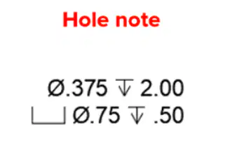
What type of hole is this hole?
Countersink Blind Hole
Counterbore Through Hole
Countersink Through Hole
Counterbore Blind Hole
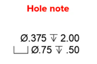
What's the diameter of the counterbore for this hole?
.375
2
.75
.5
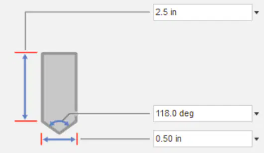
What type of hole is this hole?
Counterbore Through Hole
Simple Blind Hole
Countersink Through Hole
Countersink Blind Hole

What type of lines are shown in this image?
Hidden lines
Dimension lines
Edge lines
Construction lines

What Onshape tool is this?
Fillet
Chamfer
Extrude
Revolve
Label which feature of this part is a chamfer and which is a fillet.
Chamfer
Fillet
Choose the isometric sketch:


When a hole is always smaller than the part being placed inside of it, what type of fit is this?
Clearance
Interference
Transition
Tension
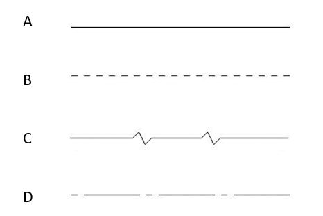
6. Which of the following represents a centre-line?
A
B
C
D
Which of these is the correct BS symbol for First Angle Projection?
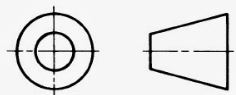
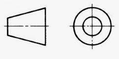
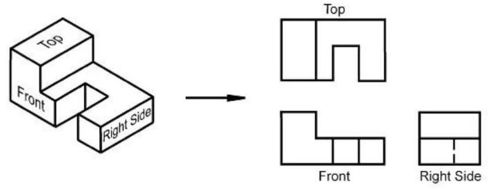
What type of projection is shown on the right?
Sketch
Isometric
Orthographic
Oblique
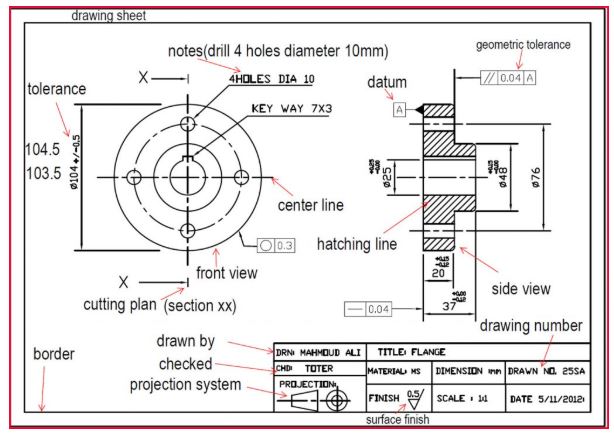
What kind of view is shown on the right hand side?
Isometric
Section
Assembly
Oblique
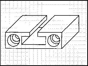
What is the correct term for this drawing type?
Isometric
3D
Orthographic
Oblique
What angle(s) do you use to draw an Isometric drawing?
30/60 degrees
45 degrees
90 degrees
45/45 degrees
What does the standard abbreviation CL stand for?
Cross Length
Closed Loop
Contour Line
Centre Line
What does ISO stand for when looking at conventional drawings?
Institute for Standards
International Science Organisation
International Standards Organisation
Independent Standards Organisation
What does the British standard BS 8888 cover?
Engineering drawings and technical product documentation
Electrical installation
Graphical symbols and flow charts
Welding and fabrication symbols
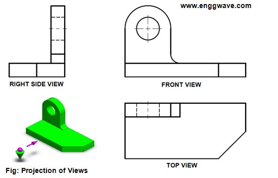
What projection is this object drawn in?
First Angle
Third Angle
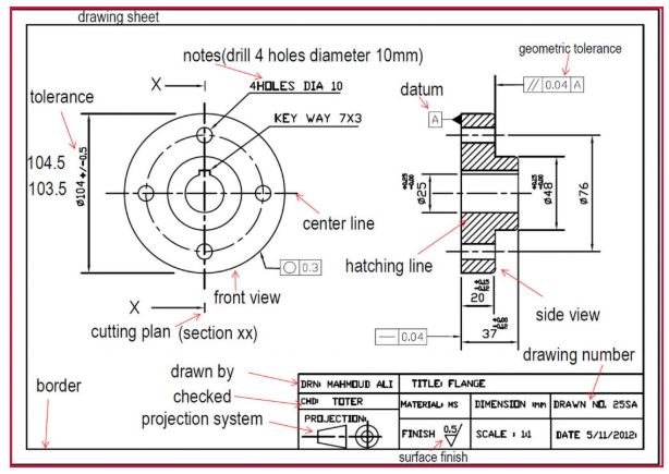
What is the required surface finish?
0.5
0.05
0.1
0.01
What angle(s) do you use to draw an Isometric drawing?
30/60 degrees
45 degrees
90 degrees
45/45 degrees
What angle(s) do you use to draw an Isometric drawing?
30/60 degrees
45 degrees
90 degrees
45/45 degrees

Which of the following views of the part shows a half section view.


Which is the correct right side view of the figure provided?


Identify the items included in an engineering drawing title box.
Drawing Title
Drawing Number
Site
Signatures
References
________is a means of representing a three-dimensional object in two dimensions.
Projection
Orthographic Project
Isometric Project
2D drawing

Is the drawing shown orthographic projection or isometric projection?
Orthographic
Isometric
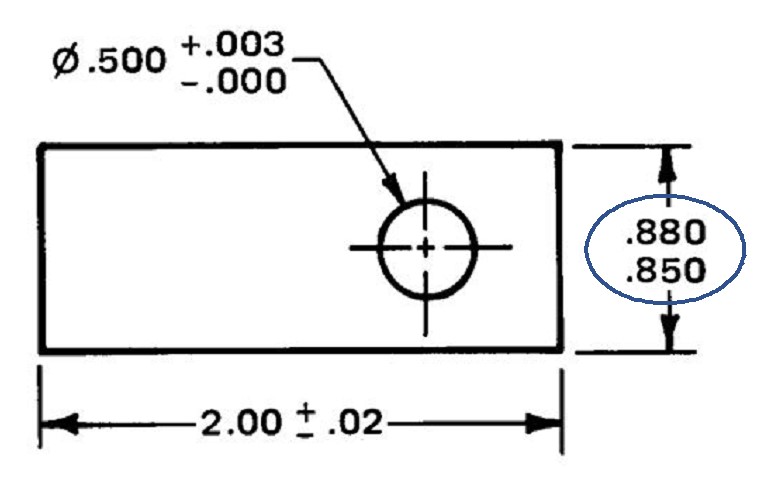
What type of tolerance is circled in this drawing?
Limit dimensions
Bilateral
Unilateral
General
What is upper limit for this tolerance? 0.250±0.01
0.250
0.240
0.260
0.02

What type of hole is called out in this image?
Radius
Counterbore
Countersink
Spotface

