
 Worksheets
Artifacts
Total questions: 134
Worksheet time: 2hrs 6mins
Produced by tissue motion (noise)
(a)
How can you fix ghosting and clutter?
(a)
“Mirror Image”.
Spectral Doppler above and below the baseline.
(a)
How can you fix crosstalk?
increase doppler gain
decrease doppler gain
increase wall filter
decrease wall filter
Insonation angle near 90 degrees and flow at the beam focus.
(a)
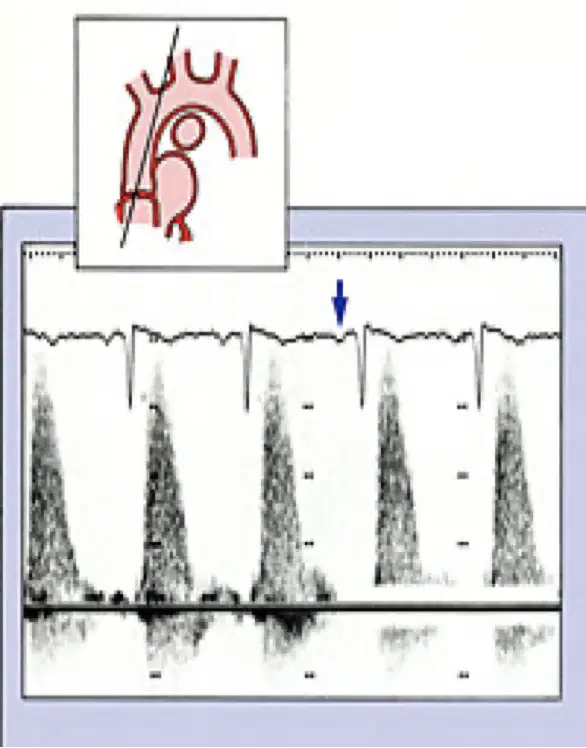
This image includes:
Crosstalk
Ghosting and clutter
Turbulence
Spectral broadening
Spectral analysis displays all the doppler shift frequencies detected from moving at different (a)
(a) is used with pulse and continuous doppler that is accurate and displays all components
(a) is used with color doppler which is less accurate than FFT and is faster than FFT
The (a) represents intravascular variation in blood flow
The (a) of the spectral line represents the range of velocities in a vessel
The width of the spectral line may vary during the normal cardiac cycle narrowing during __ and __ during diastole
(a)
(a) consists of a wide range of velocities includes reversed flow components and is readily appreciated
Fill in of the window associated with turbulence
(a)
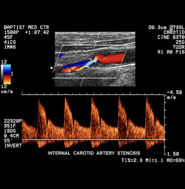
This shows
(a)
Turbulent flow is visible as (a)
Where is turbulent flow considered normal?
Everywhere
Bifurcations
Legs
Arms
The (a) is a quantitive, doppler derived measurement
Resistive index reflects the vascular (a) of a vessel
RI = (PSV-EDV)/PSV
(a)
The (a) is quantitve and is where MV is the mean flow velocity during the cardiac cycle
PI = (PSV-EDV)/MV
(a)
What do RI and PI provide information regarding?
Blood flow and resistance
Blood flow and pulse
Pulse and resistance
Artifacts are (a) representations of anatomy or motion caused by some problematic aspect of the imaging technique
(a) are incorrect representations of anatomy or motion caused by some problematic aspect of the imaging technique
Artifacts are representations that are __ __
(a)
Artifacts are representations that are (a)
Artifacts are representations that are
(a)
Artifacts are representations that are
(a)
Ultrasound displays rely on (a) to assign the location and intensity of each echo
Assumptions can cause artifacts when assumed conditions are (a)
Sound travels at 1540m/s
(a)
Sound beam travels directly to a reflector and back
(a)
Sound travels in a straight line
(a)
All sound attenuation exactly 0.5 db/cm/MHz
(a)
Reflections arise only from structures positioned in the beams main axis
(a)
The strength of a reflection is related to the characteristics of the tissue creating the reflection
(a)
The depth of an object is directly related to the amount of time for an ultrasound pulse to return to the transducer as an echo,
(a)
Axial and lateral resolution are (a) artifacts
Grating and side lobe are (a) artifacts
Mirror image, comet tail, and ring down are (a) artifacts
Range ambiguity and refraction are (a) artifacts
Section thickness, speckles, and ring down are (a) artifacts
Enhancement/Focal enhancement, and shadowing/edge shadow are (a) artifacts
(a) is multiple equally spaced echoes caused by the BOUNCING of echoes BETWEEN strong reflectors
With reverberation, echoes are placed (a) the real reflector
Reverbation artifacts are (a) to the main axis
The arrow in this image is pointing to WHICH type of artifact?
Enhancement
Mirror image
Reverberation
Shadowing
This image shows
(a)
(a) is associated with the assumption: sound travels directly to a reflector and back
Which of the following are TYPES of reverberation?
Comet tail
Shadowing
Ring down
Mirror image
The (a) artifact is a form of reverberation that includes close spaced, discrete echoes
Comet tail is a hyperechoic line (a)
(a) is created by strong reflectors like surgical clips
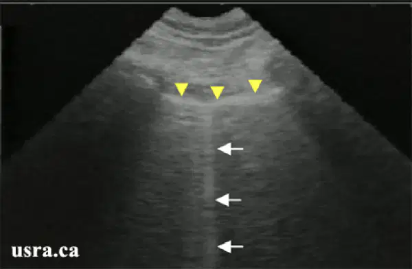
The arrows are pointing to (a) artifact
When will comet tail most LIKELY occur?
In mediums with low propagation speeds
In mediums with high propagation speeds
The assumption with comet tail is that:
Speed of sound is constant
Sound travels directly to the transducer and back
Tissue interface
Imaging plane is very thin
The (a) artifact includes closed spaced, discrete echoes that CANNOT be separated
Hyperechoic line downward that is created by (a) artifact
Ring down artifacts are created by gas bubbles are are (a) to sound beams main axis
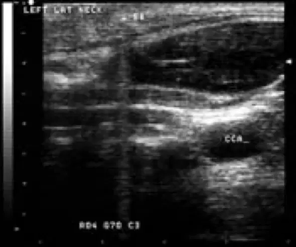
This image shows:
(a)
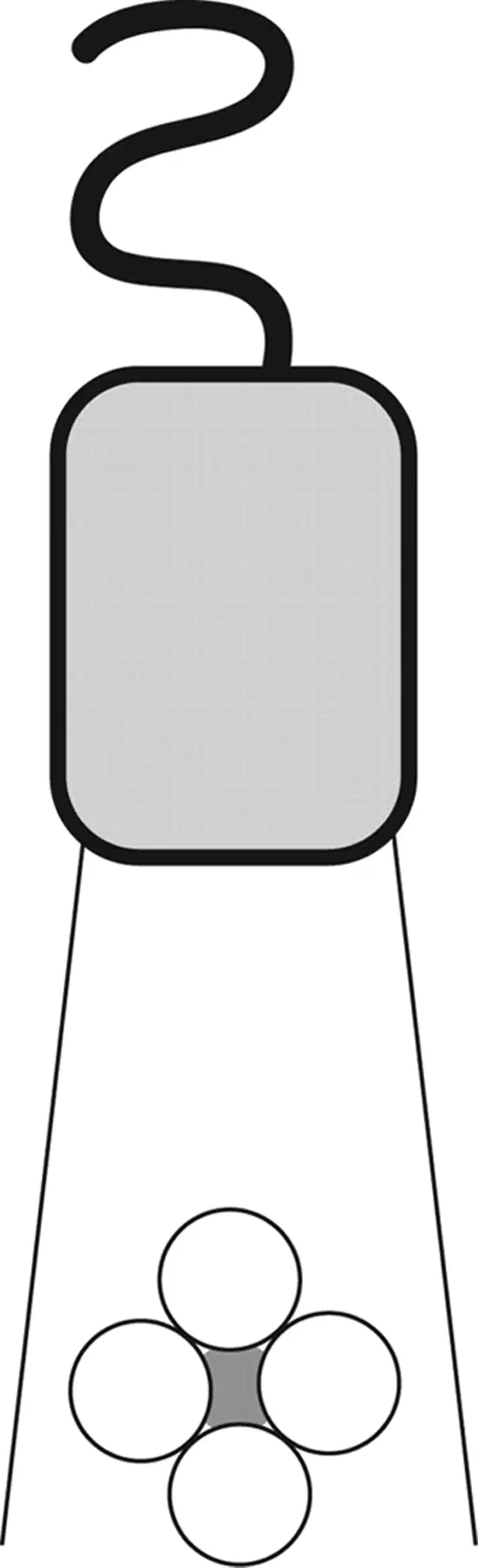
This diagram is an example of the (a) artifact
Shows structures that are on one side of a strong reflector as being present on the other side as well describes the (a) artifact
With mirror image artifacts the artifact will appear (a) than the real structure
In a mirror image, the strong reflector lies on a (a) between the transducer and artifact
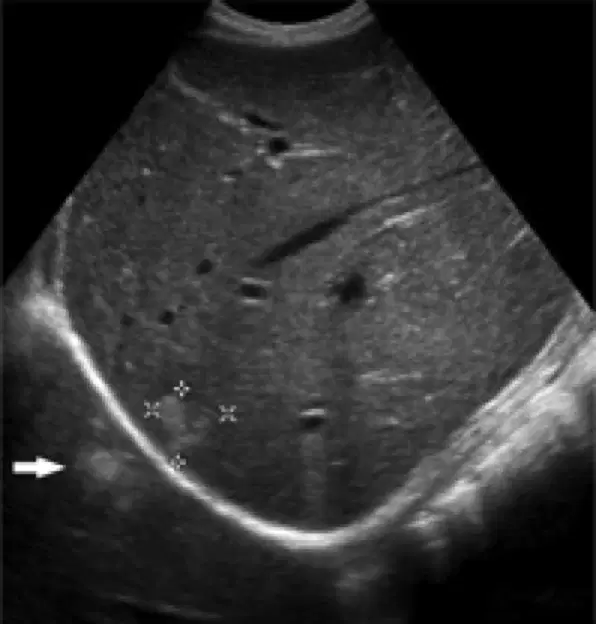
This image shows the (a) artifact
The assumption that is correlated with (a) is: sound travels in a straight line AND sound travels directly to a reflector and back
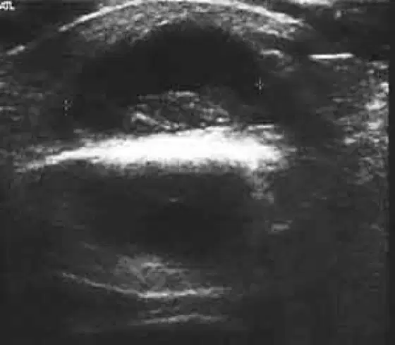
This image shows:
(a)
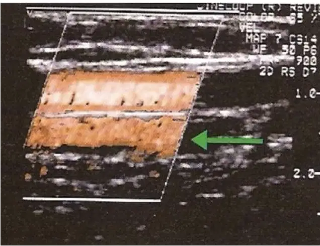
This image shows:
(a)
The echoes from the deeper reflective interface take longer to return to the transducer and are misplaced on the display
(a)
(a) are beams propagating from a single element in different directions from the primary beam
Side lobes are created by (a) transducers
(a) are additional beams emitted from an array transducer
Which lobe artifact is stronger than the other?
Side lobe
Grating lobe
Side and grating lobes are (a) than the primary beam unless they hit a strong reflector
Lobe artifacts (a) LATA
Which two ways go along with reducing lobe artifacts?
Wall filter
Doppler gain
Subdicing
Apodization
Dividing each PZT element into a small piece =
(a)
Differential excitation = A
(a)
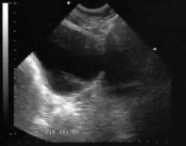
A (a) artifact is present in this image

This diagram displays (a) artifact
The assumption that is correlated to side and grating lobes is that:
Sound beams travel in a straight line
Speed 1540 m/s
Reflectors arise from structures along the beams main axis
(a) artifact displaces reflectors laterally from their original location
(a) could occur with a change of velocity when beam travels through tissues with different density and elastic properties
In refraction, does perpendicular incident ultrasound energy encounter an interface between two materials with different speeds of sound?
yes
no
When refraction occurs, the incident beam changes (a) .
The change in direction caused by refraction is dependent on:
Snells law
Difference of velocities
Angle of incident beam
Oblique incidence
Refraction is described by (a)
Which assumption is related to refraction?
Speed of sound constant
Sound travels to the reflector and back
Sound travels in a straight line
With refraction, the object in the path of the refracted portion is misplaced bc the processor assumes:
(a)
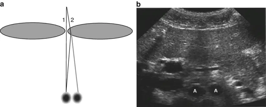
This image shows the (a) artifact
Refraction artifacts affect the (a) resolution
(a) artifacts appear to be side by side of the same reflector
Refraction can cause the artifacts to be positioned (a)
(a) occurs when a sound wave travels at a speed other than 1540 m/s
When the assumed speed of 1.54 mm/us is incorrect, the 13 us/cm rule is ALSO incorrect
(a)
When the medium has a (a) speed of sound, the distance to the reflector will be smaller and the reflector will be TOO close to the transducer
When the speed of sound is (a) in a medium the reflector will be located far away from the transducer
Sound travels at a speed of exactly 1.54 mm/us
(a)
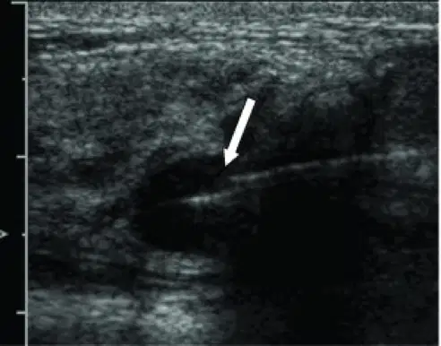
The arrow in this image is pointing to
(a)
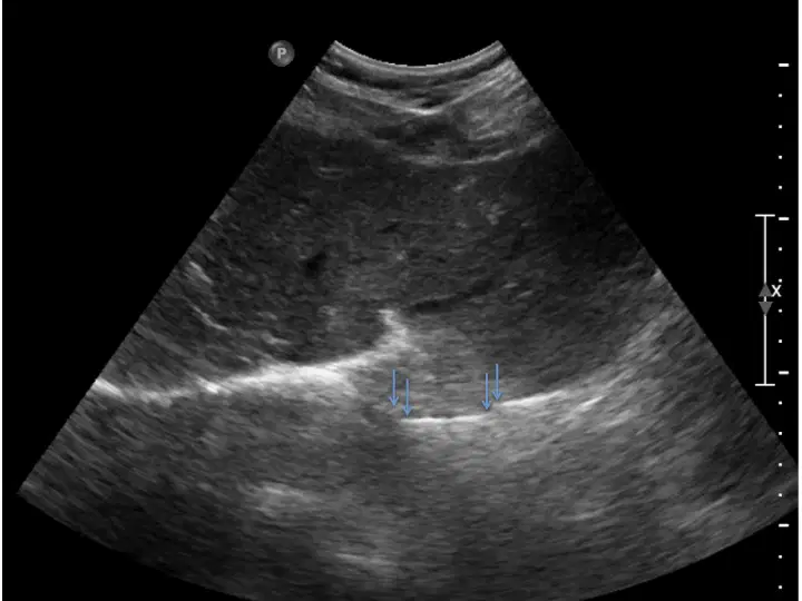
This image includes a (a) artifact
(a) describes artifactual images from above or below the assumed plane of scanning
Section thickness is related to the (a) of the beam (perpendicular to the scan plane)
(a) artifacts fill in anechoic structures
the assumption for (a) is that the scan plane is very thin
(a) is reduced by thinner planes (1 and 1 half transducer array)
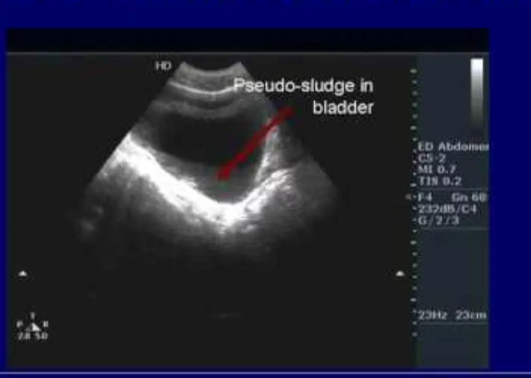
This image shows (a)
With a (a) artifact, the texture seen on image may not correspond to the tissues texture
Speckle results from (a) effects between multiple reflectors received simultaneously which can add together
(a) is noise resulting from the constructive and destructive interference of small sound wavelets
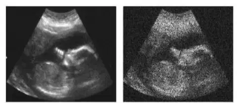
This image includes the (a) artifact
The (a) artifact is when the beam is wider than separation between two reflectors positioned side by side
With LATA, two reflectors show as (a)
The (a) artifact is LEAST likely at the focus of the beam
This artifact occurs when two reflectors are close together in the main axis of the beam and the pulse is long
(a)
With axial resolution only (a) reflection will show
(a) frequency transducers improve axial resolution artifact
When the ultrasound beam encounters a focal point lateral that attenuates sound to a greater or lesser extent than the surrounding tissue
(a)
The strength of the beam distal to this structure will be either weaker or stronger than the surrounding field
(a)
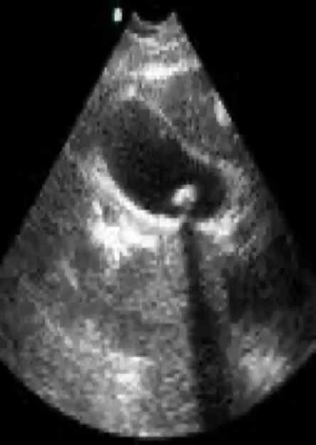
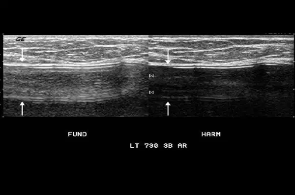
This image shows:
(a)
The assumption that the intensity of a reflection is related to the tissue creating the reflection is invalid with ALL (a) artifacts
Hypoechoic region arising from the border of a curve structure
(a)
What causes edge shadow?
Gallstones
Beam diverging w lower intensity
Beam diverting w high intensity
Refraction
Shadow by "refraction" refers to
(a)
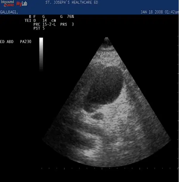
This image shows:
(a)
Occurs when the ultrasound beam encounters a focal weakly attenuating structure within the imaging field
(a)
Regarding enhancement, the amplitude of the beam beyond this structure is (a) than the beam amplitude at the same depth in the rest of the field
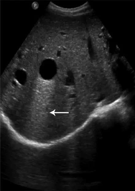
This image shows
(a)
(a) involves side to side regions being brighter than tissues at other depths. Appears as a line across the screen (almost like a TGC was increased in only 1 spot)
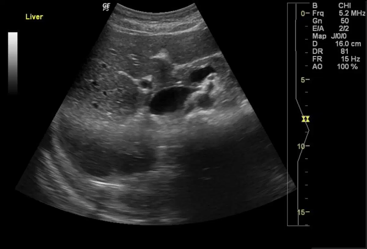
This image shows:
(a)
All of the following artifacts result in the placement of too many echoes except
Shadowing
Reverberation
Mirror image
Grating lobes
Which artifact produces an image with an incorrect number of reflectors
Propagation speed error
Multipath
Enhancement
Side lobes
Which artifact is unrelated to the dimensions of an ultrasound pulse?
LATA
depth resolution
slice thickness
refraction
Two reflections, one true, and one artifact are displayed on an ultrasound image. In the body , only one structure is present. The correct reflection and the artifact are found side by side. What is the most likely cause of this artifact
Mirror image
Grating lobe
Enhancement
Multipath

