
 Worksheets
Read Schematic Diagrams - Objectives
Total questions: 24
Worksheet time: 12mins
Electrical power is calculated by multiplying voltage by which of the following?
Current
Resistance
Capacitance
Inductance
What does a schematic diagram show?
Only the physical appearance of components
Circuit paths and components using lines and symbols
The color of wires
The size of the battery
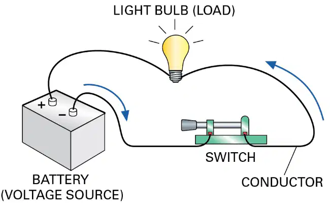
In the pictorial diagram, which component is labeled as the voltage source?
Light Bulb
Switch
Battery
Conductor
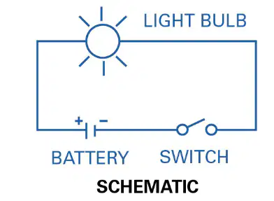
In a schematic diagram, a ________ is represented by a circle with lines radiating from it.
light bulb.
resistor.
battery.
switch.

Which symbol represents an Ammeter?
𝑉
𝑊
𝐴
Ω
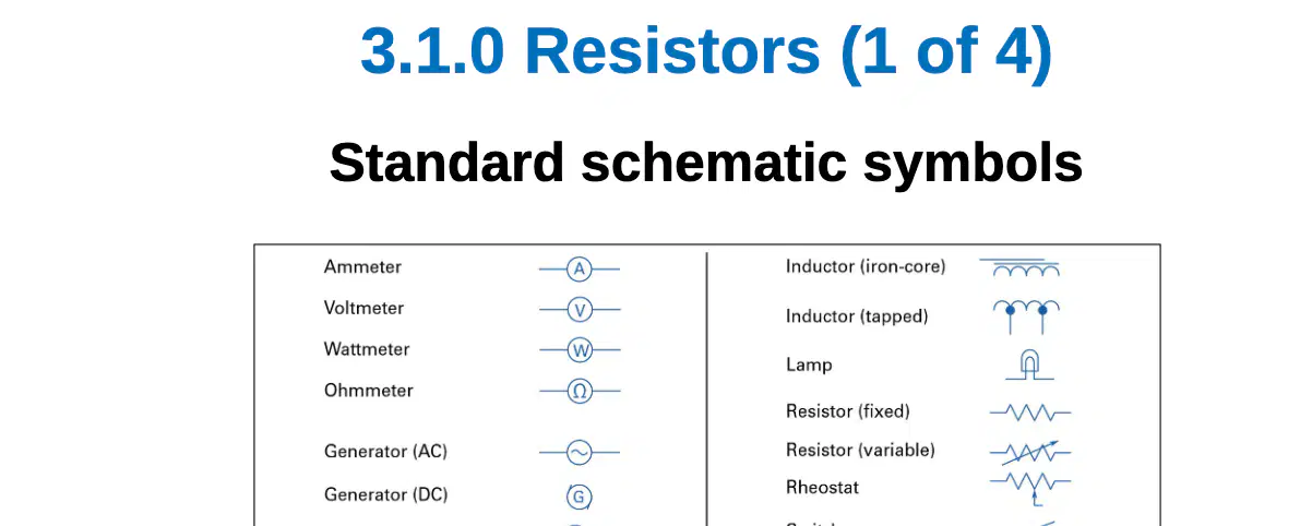
Which symbol represents a Voltmeter?
𝑉
𝑊
𝐴
Ω
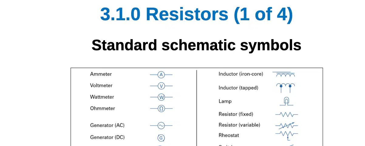
Which symbol represents a Wattmeter?
𝑉
𝑊
𝐴
Ω
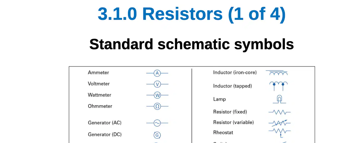
Which symbol represents an Ohmmeter?
𝑉
𝑊
𝐴
Ω
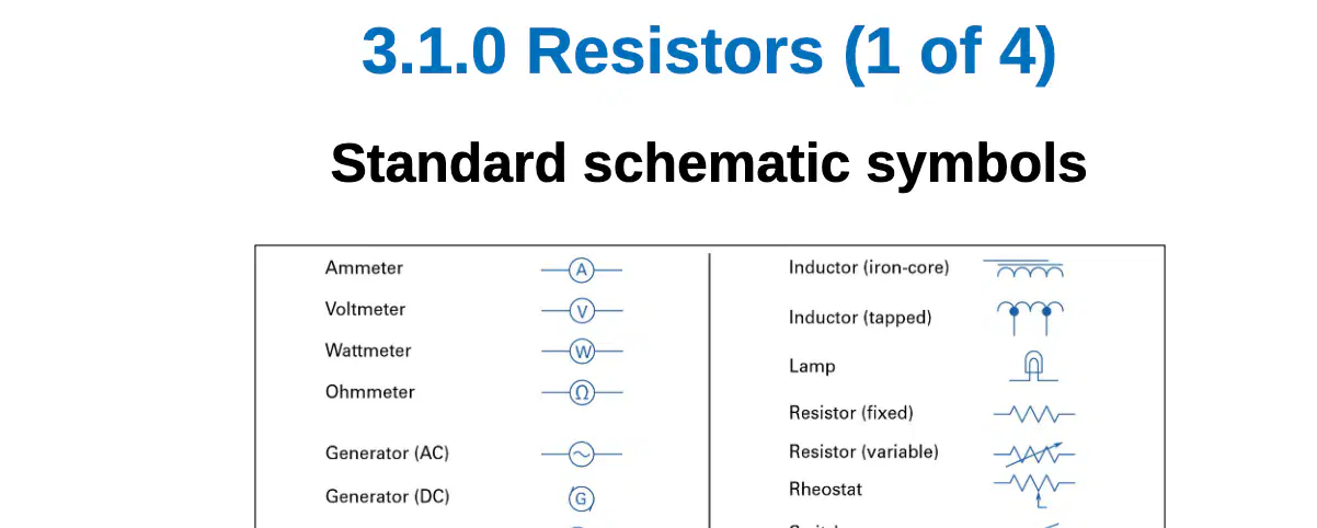
Which symbol represents a Generator (AC)?
Circle with sine wave
Circle with G
Circle with B
Circle with straight line
Resistors are typically covered in _________.
porcelain
plastic
glass
rubber
Which of the following is used to adjust resistance using a movable contact?
Fixed resistor
Variable resistor
Capacitor
Inductor

Identify the component shown in the right diagram:
Potentiometer
Rheostat
Most household circuits are wired in _________.
parallel
series
tandem
circular
The type of circuit determines the method used to calculate the _________.
resistance
voltage
current
power
Inline ammeters are connected in series with the circuit. What is the main reason they are much less common?
They are more expensive
They require the circuit to be opened
They are less accurate
They are larger in size
Inline ammeters are connected in ______ with the circuit.
series
parallel
diagonal
reverse
A voltmeter should be used with the power off.
True
False
A ________ is connected in parallel with the component or circuit to be tested to check whether the correct voltage is being supplied.
voltmeter
ammeter
resistor
transformer
Resistance is measured using an ohmmeter with the power to the circuit ________.
shut off
turned on
at maximum
disconnected
Ohmmeters can be used to check the resistance of which of the following?
Motor windings
Electrical continuity in a circuit
Both A and B
None of the above
The power to the circuit should be shut off when measuring resistance with an ohmmeter.
True
False
What is the primary use of voltage testers?
To measure the exact voltage in a circuit
To check for the presence of voltage when troubleshooting a circuit or to make sure the voltage is off before handling components
To repair electrical circuits
To increase voltage in a circuit
True or False: Voltage testers are meant for precise circuit measurements.
True
False
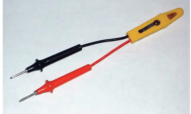
What is shown in the image below?
Voltage tester
Light bulb
Circuit breaker
Resistor

