
 Worksheets
Cold water revision 6035
Total questions: 54
Worksheet time: 27mins
State which regulation set legal requirements for the design, installation, operation and maintenance of plumbing systems, water fittings and water-using appliances. They have a specific purpose to prevent misuse, waste, undue consumption or erroneous measurement of water and, most importantly, to prevent contamination of drinking water.
Water Supply (Water Fittings) Regulations 1999
Water Industry Act 1991
Building Regulations Part G: Sanitation, Hot Water Safety and Water Efficiency
BS 8558: Guide to the design, installation, testing and maintenance of services supplying water
Identify which British standard is the Specification for installations inside buildings conveying water for human consumption.
12056
1010
8000
806
Identify which British standard is the Guide to the design, installation, testing and maintenance of services supplying water for domestic use within buildings and their curtilages.
806
1212
6700
8558
State which organisation produces the water regulations, and the water fittings and material directory.
Water Regulations Advisory Scheme (WRAS)
Drinking Water Inspectorate (DWI)
Ofwat
British Standards Institution (BSI)
Identify what the abbreviation WRAS stands for?
Water requirement and standards
Water regulation advice scheme
Water regulation advisory scheme

Identify the type of well shown in the diagram of geological strata where water rises due to pressure from a confined aquifer.
Shallow dug well
Deep bore well into pervious strata
Artesian well
Land spring
Identify which chemical is found in permanent hard water.
Calcium sulfate
Calcium bicarbonate
Sodium chloride
Potassium nitrate
Identify which chemical is found in temporary hard water.
Magnesium sulfate
Calcium bicarbonate
Sodium carbonate
Calcium chloride
State the main problem caused by temporary hard water when heated above 65 degrees.
It forms scale deposits from precipitated calcium carbonate (Limescale)
It becomes highly corrosive and dissolves metals rapidly
It turns blue and loses transparency
It evaporates instantly without leaving residue
Describe the easiest way to determine if you have hard or soft water.
Taste the water for saltiness
Observe its color in a clear glass
Use a soap‑lather test to see how easily suds form
Boil briefly and check the temperature change
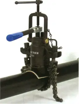
Identify the fitting shown and select the best description of where it is used. The image shows a chain-mounted device clamped to a pressurized pipe with a valve body and boring stem (hot tapping setup).
Hot tapping machine used to create service connections on pressurized water mains without shutting down flow
Gate valve used to isolate individual plumbing fixtures within a building
Compression coupling used to join two cut pipe sections in a non-pressurized condition
Pressure-reducing valve installed at a building’s water service entry to lower inlet pressure
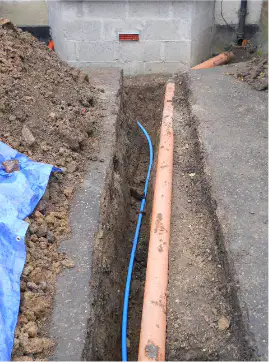
Identify the type of underground pipe shown in the trench, and the feature that indicates it carries water.
Blue MDPE service pipe identified by its blue color coding
Yellow MDPE gas pipe identified by its yellow color coding
Black polyethylene electrical duct identified by cable markings
Copper tube identified by metallic finish
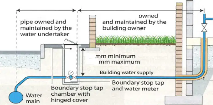
From the service pipe diagram, what is the minimum and maximum burial depth required for a water service pipe?
750 mm minimum and 1350 mm maximum
300 mm minimum and 600 mm maximum
600 mm minimum and 900 mm maximum
900 mm minimum and 1800 mm maximum

From the service pipe diagram, what is the correct name for the pipe that runs from the water main to the boundary stop valve?
Communication pipe
Supply pipe
Service duct
Riser pipe
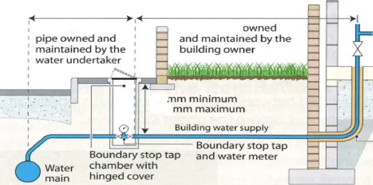
From the service pipe diagram, what is the correct name for the pipe that runs from the boundary stop valve to the domestic property?
Supply pipe
Communication pipe
Tracer wire
Service duct

From the service pipe diagram, what minimum horizontal distance should an uninsulated service pipe be kept from the external wall when entering the property?
150 mm
300 mm
450 mm
600 mm
Identify which type of copper can be used underground.
R220 soft copper
R250 half hard
R220 soft coil micro-bore
R290 hard
Where should the internal stop valve be installed?
As close as practicable to the point of entry on the rising main, before any branches, and easily accessible
Behind a sealed panel in a locked cupboard away from the entry point
Outside near the boundary stop tap
In the loft next to the cold water storage cistern
Select the two places where you could isolate the water to the service or supply pipe.
Boundary stop tap (external)
Internal stop valve (inside the property)
Valve beside the loft cold water cistern
Garden tap bibcock
Identify three areas where you would find the water meter. Select all correct locations.
On the public footpath or pavement in a boundary box
Inside the kitchen base unit near the stop tap
Mounted in an external wall meter box
Under the bath next to the trap
In the attic near the cold-water storage cistern
Which type must the drain off valve be?
Compression-type drain-off cock fitted to the pipework
Double check valve in the rising main
Ball float valve inside the cistern
Screw-down bib tap at the basin
State the most cost effective procedure to repair the stop valve when the valve jams.
Replace the entire stop valve assembly
Service the stop valve and renew the washer/jumper to free the spindle
Install a new section of pipe and relocate the valve
Call the water authority to replace the street main
Identify where a drain off valve should be installed apart from above the stop valve.
At the lowest point of the system to allow complete drainage
On the highest riser to vent air
Next to each tap outlet
Inside the boiler casing
When installing appliances identify the two key tests to be carried out. Select both.
Flow rate test at the outlet
Static/dynamic water pressure test
Continuity test of electrical bonding
Water hardness (limescale) test
Leak-detection using dye tablets
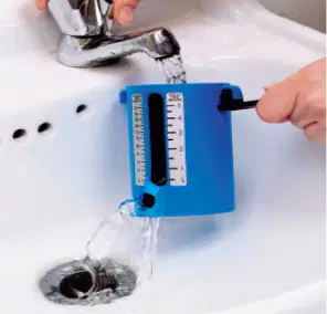
Identify the equipment shown in the left-hand photo: a person holds a blue device under a running basin tap to collect and measure discharge.
Flow cup for measuring outlet flow rate
Pressure reducing valve
Handheld TDS meter
Stop valve key

Identify the equipment shown in the right-hand photo: a white-and-blue fitting with a pressure gauge connected to pipework.
Pressure gauge on a pressure-reducing valve
Inline water meter
Thermostatic mixing valve
Double check valve assembly
Identify factors that may impact measurements. Select all that apply.
Partially closed stop valve or service valve
Fouled tap aerator or restricted outlet
Simultaneous demand elsewhere on the system
Long small‑bore pipe runs causing pressure drop
Ambient temperature around the gauge
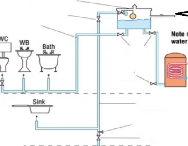
Select the advantages of the illustrated plumbing system. Choose all that apply.
Continued supply during short mains interruptions via a storage cistern
Higher outlet pressures at all fixtures compared with mains
Reduced risk of backflow contamination of the mains
Quieter operation at taps and WCs due to lower pressure
Eliminates the need for a hot water storage vessel
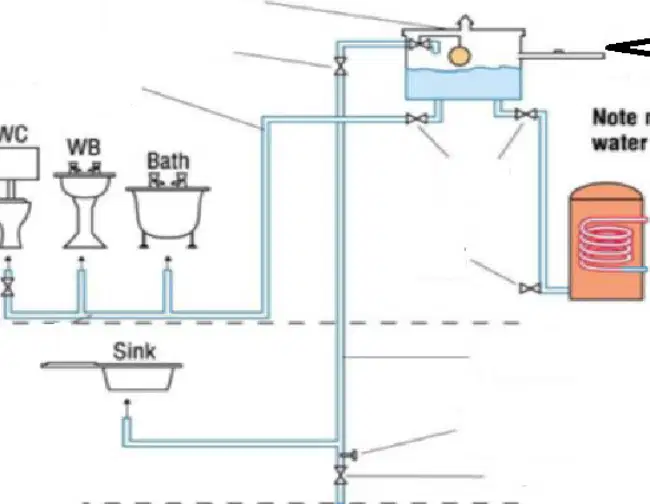
Select the disadvantages of the illustrated plumbing system. Choose all that apply.
Increased risk of stagnation in stored cold water
Greater space and maintenance needs for the cistern and venting
Higher installation complexity with additional pipe runs
Delivers constant mains pressure at all outlets
Automatically complies with all regulations without product approval
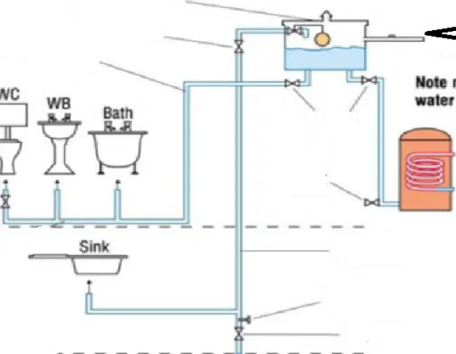
What is the easiest way to determine whether the plumbing system is direct or indirect?
Check whether most fixtures are supplied from a storage cistern rather than directly from the mains; if so, it is indirect
Measure the temperature of hot water leaving the cylinder; if it is vented, the system is direct
Verify that the sink is supplied from the mains; if so, the system is direct
Count the number of bathrooms; more than one means the system is indirect
Identify the reasons for using approved water fittings in cold water plumbing systems. Choose all that apply.
Prevent contamination and safeguard potable water quality
Ensure compliance with legal and regulatory standards
Improve durability and safety through tested materials and design
Guarantee higher flow rates than unapproved fittings in every installation
Eliminate the need for installation by qualified personnel
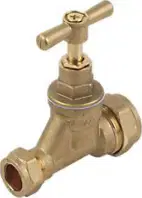
Identify this fitting and a typical location where you would find it. The image shows a brass stop-tap with a T-handle and compression ends.
Service stopcock on the incoming mains supply
Lever-operated ball valve on appliance feed lines
Gate valve on heating circuit flow/return
Double check valve on hose bibb supply

Identify this fitting and a typical location where you would find it. The image shows a chrome lever-operated ball valve with compression ends.
Lever ball valve used for isolating cold or hot water feeds to appliances
Service stopcock used at the water meter or main entry
Gate valve used on gravity-fed heating systems
Double check valve installed on outdoor tap supplies
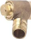
Identify this fitting and a typical location where you would find it. The image shows a small brass right‑angle fitting with a cap and spigot, used for draining down.
Drain‑off cock installed at low points to drain plumbing or heating systems
Service valve installed under basin taps
Double check valve to prevent backflow on hose connections
Gate valve used to isolate a circuit
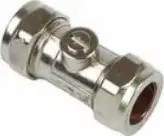
Identify this fitting and a typical location where you would find it. The image shows a compact inline chrome service valve with a screwdriver slot.
Service/isolating valve fitted on basin and sink tap supplies
Lever ball valve for appliance isolation on larger bore pipe
Double check valve on outside tap line
Gate valve on gravity systems
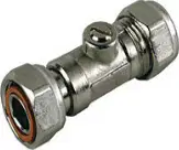
Identify this fitting and a typical location where you would find it. The image shows an inline chrome body with a bulged center section indicating a check mechanism.
Double check valve used to prevent backflow, commonly on hose bibb supplies
Service stopcock at incoming mains
Gate valve on heating circuits
Drain‑off cock at low points
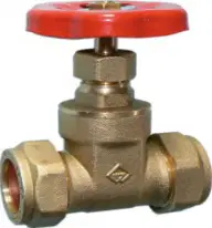
Identify this fitting and a typical location where you would find it. The image shows a bronze gate valve with a red wheel handle.
Gate valve typically used to isolate circuits on gravity-fed (low‑pressure) systems
Lever ball valve for appliance isolation
Service stopcock at main entry
Double check valve on hose bibb supply
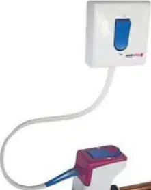
Identify this fitting and where you would find it. The image shows an electrically controlled inline valve with a remote wall switch connected by a cable.
Remote‑operated solenoid shut‑off valve used for rapid isolation of a water supply
Service stopcock fitted at the meter
Manual gate valve on gravity systems
Double check valve preventing backflow
Identify which of the above fittings is used on low pressure systems.
Gate valve with red wheel handle
Lever‑operated ball valve
Service stopcock
Double check valve

Identify the following components: In the upper valve cross‑section, which part seals against the seat to stop flow through the body?
Disc/washer
Spindle
Gland packing
Handle

Identify the following components: In the upper valve cross‑section, which component is the threaded rod that moves the disc up and down when the handle is turned?
Spindle
Seat
Olive
Compression fitting
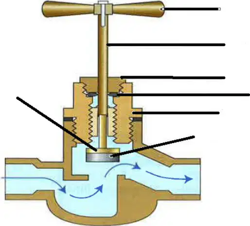
Identify the following components: In the upper valve cross‑section, which component provides the leak‑tight seal around the spindle within the stuffing box/gland?
Gland packing
Seat
Disc/washer
Body

Identify the following components: In the upper valve cross‑section, which fixed surface does the disc/washer press against to shut off flow?
Seat
Handle
Olive
Compression fitting
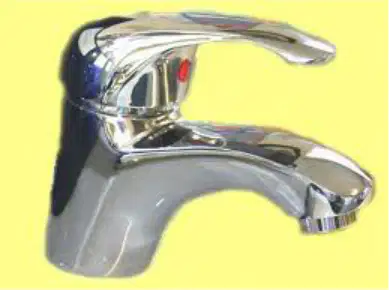
Identify the three types of taps: What type of tap is shown in the photo of the single‑handle chrome mixer mounted on a basin?
Single‑lever mixer
Pillar tap
Bibcock
Garden hose tap
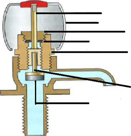
Label the following diagrams: In the cross‑section of the float‑operated valve used on a cold water storage cistern, which component moves vertically inside the body to open and close the water entry?
Spindle/plunger
Float arm
Valve seat
Overflow tube
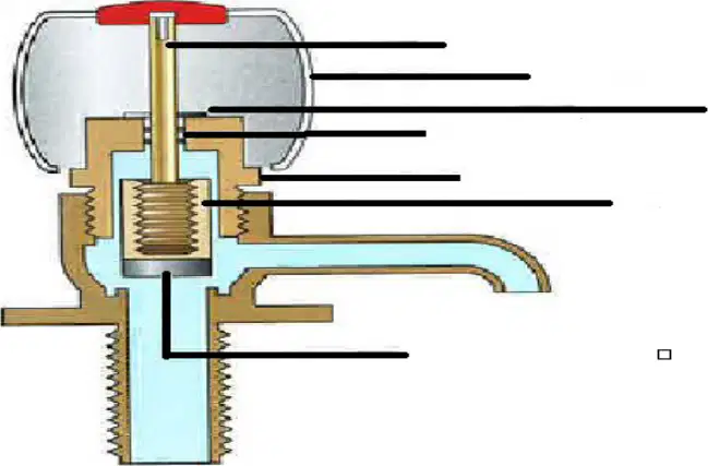
Label the following diagrams: In the float‑operated valve cross‑section, which soft component seals against the brass seat to stop the incoming water when the cistern is full?
Washer/diaphragm
Threaded body
Vent cap
Outlet elbow

State the main considerations when installing a cold water cistern. Which of the following features is required to prevent vermin entering through the vent?
Screened vent
Unscreened overflow
Open vent without grommet
Leaving the vent pipe submerged
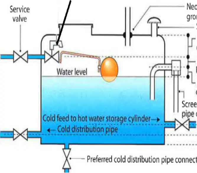
State the main considerations when installing a cold water cistern. Which component must have a neoprene rubber sealing grommet fitted around it?
Vent pipe
Cold feed to hot water cylinder
Distribution pipe clip
Service valve

State the main considerations when installing a cold water cistern. Which positioning requirement applies to the overflow/warning pipe and the normal water level?
Maintain a specified distance between the overflow and the water level
Keep the overflow permanently below the water line
Connect the overflow to the hot water cylinder
Seal the overflow with a service valve
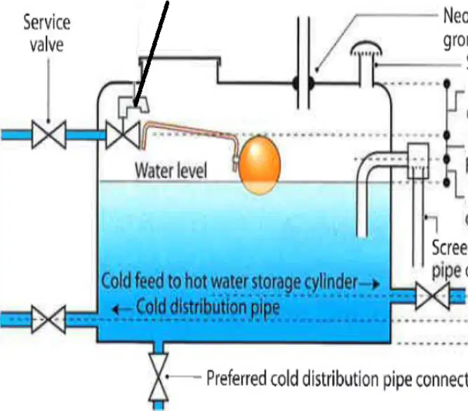
Label the diagram below: In the cistern installation schematic, which connection is shown as the preferred outlet for distributing cold water to the system?
Preferred cold distribution pipe connection
Screened vent
Float‑valve connection
Service valve on the feed
State the requirements for a 1000 L cold water cistern. Select all that apply.
A close-fitting, removable lid with an access hatch
Screened overflow and vent to exclude insects and debris
Insulation to limit water temperature rise in the loft/storage area
A rigid, level support base and bracing adequate for the full mass when filled
Use of solvent or petroleum-based jointing compounds on plastic fittings
Identify the tool used for drilling holes into the cold water cistern.
Hole saw with arbor
Twist drill bit
Spade (flat) wood bit
Masonry drill bit
State which jointing material shouldn’t be used with plastic cold water cisterns.
Petroleum-based jointing compound
PTFE tape
Neutral-cure silicone sealant
Rubber washers with backnut
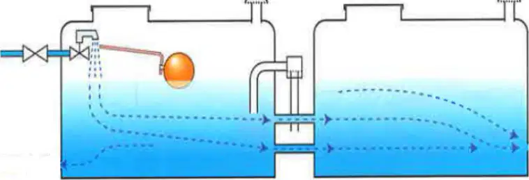
Identify in the diagram where you would install the distribution pipe to prevent stagnation.
At the top near the inlet and float valve in the first cistern
From the base at the outlet end of the second cistern, opposite the inlet, drawing from the lower zone
Mid-level connection between the two cisterns
Connected to the overflow at the top of either cistern

