
 Worksheets
Soldering Question Bank
Total questions: 97
Worksheet time: 49mins
Which feature makes a soldering iron safer for sensitive electronics work?
High-watt fixed output only
Electrostatic discharge safe design
Extra-wide tip for faster heat
Non-metallic tip material
Which statement best describes fixed versus variable power soldering irons?
Fixed power allows tip replacement anytime
Variable power lets you control tip temperature
Fixed power heats faster than variable models
Variable power uses lower wattage for all jobs
For small electronics jobs, which fixed power rating is commonly recommended?
10-watt for micro soldering
25-watt for routine small work
60-watt for light repairs
100-watt for delicate circuits
Why are high-power, temperature-controlled irons preferred for complex projects?
They reduce ESD risk by grounding
They maintain consistent tip heat
They eliminate need for flux
They cool quickly after use
Which choice explains a key benefit of variable temperature control on a soldering iron?
Prevents oxidation of the copper board
Allows matching heat to job size
Automatically feeds solder to joint
Removes fumes without ventilation
Which alloy composition is most common for beginner electronics soldering?
50% tin and 50% lead
60% tin and 40% lead
70% tin and 30% lead
90% tin and 10% lead
Which alloy has the lowest melting temperature among common tin‑lead solders?
60/40 tin‑lead alloy
63/37 tin‑lead alloy
57/43 tin‑lead alloy
65/35 tin‑lead alloy
At what temperature does 60/40 solder become pliable, even though it doesn’t fully melt until higher?
321 °F (161 °C) pliable
361 °F (183 °C) pliable
371 °F (189 °C) pliable
401 °F (205 °C) pliable
Which characteristic of lead‑free solder makes it harder to use than tin‑lead solder?
Lower melting point than tin‑lead
Poorer wetting of copper surfaces
Higher electrical resistance overall
Incompatible with flux paste
Which lead‑free alloy composition is commonly used under RoHS regulations?
96.5% tin, 3.5% silver
63% tin, 37% lead
60% tin, 40% lead
90% tin, 10% copper
Why must ventilation or a respirator be used when soldering with leaded solder?
Flux fumes contain silica dust
Lead content poses inhalation hazard
Tin reacts forming ozone gas
Heat releases carbon monoxide
Which statement correctly compares 63/37 versus 60/40 solder behavior?
63/37 melts sharply at eutectic point
60/40 has lower melting temperature
63/37 remains pasty over wide range
60/40 fully melts at 183 °C
Which reason justifies choosing lead‑free solder despite higher difficulty?
It requires less flux for joints
It aligns with safety regulations
It produces weaker mechanical joints
It always costs less than tin‑lead
Which statement about availability of solder formulations is accurate?
Only leaded solder is legal online
Both types are widely available online
Lead‑free is store only, not online
Tin‑only exists only by special order
Which scenario best matches using a 100‑watt fixed power soldering iron?
Fine‑pitch microcontroller pins
Large jobs with heavy cabling
Small repairs on hobby kits
Surface‑mount resistor rework
Which primary purpose does flux serve during soldering on electronic assemblies?
Remove oxidation and promote wetting
Increase solder melting temperature
Strengthen the joint mechanically
Insulate traces from heat damage
Which flux type is intended to be left on the joint because its residue is non-corrosive and non-conductive?
No-clean flux
Water-soluble flux
RA flux
RMA flux
After using rosin-based fluxes, what is the recommended action regarding residue?
Clean with isopropyl or remover
Leave it to protect the joint
Bake the board to harden it
Neutralize with alkaline solution
Water-soluble flux typically requires which post-soldering step to prevent damage?
Thorough cleaning with water
Immediate reflow at higher heat
Coating with conformal varnish
Cooling with compressed air
In through-hole soldering, a component lead is primarily connected to what feature on the PCB?
A plated pad around the hole
A solder mask opening only
A heat sink via the chassis
A silkscreen reference mark
What distinguishes a plated-through hole from a non-plated hole on a PCB?
Metal plating connects top and bottom
Only the top pad exists
The hole is larger for cooling
It is covered by solder mask
Which statement best describes a solder joint in electronics regarding structural strength?
Provides electrical connection, not mechanical strength
Provides high vibration resistance
Acts as the primary structural fastener
Eliminates the need for clamps or ties
When soldering wires to lugs, what should be ensured before applying solder?
A firm mechanical connection
Flux with highest activity
Preheating the entire wire
Using lead-free solder only
Which tool is most suitable for holding tiny components steady while soldering?
Tweezers or needle-nose pliers
Large adjustable wrenches
Plastic spudgers only
Magnetic pickup tools
What is the main reason to use a clamp or stand for the board during soldering?
Stabilize the board for precise work
Increase solder melting speed
Reduce flux activity chemically
Prevent component oxidation
Which statement about RA and RMA fluxes is most accurate for electronic soldering?
Higher activity requires residue removal
They are always water-neutralized
They cannot be used on PCBs
They strengthen joints mechanically
Why is plumbing flux inappropriate for electrical soldering?
It is chemically incompatible
It melts at too low a heat
It lacks any cleaning action
It is electrically conductive
A PCB trace primarily functions as which element in a circuit?
Low-resistance conductive path
Mechanical mounting bracket
Thermal barrier for components
Insulating overlay for pads
If a component lead is inserted in a non-plated hole, how is electrical connectivity ensured?
Soldering to the pad on that side only
Relying on flux residue conduction
Using clamps to force current flow
Leaving the joint unsoldered
During assembly, residues from active flux remain on a board. What is the best plan to prevent long-term corrosion or malfunction?
Clean residues thoroughly after soldering
Apply more solder to seal residues
Increase iron temperature on next joints
Cover residues with solder mask
Which step verifies a resistor’s suitability before soldering?
Checking body size visually only
Reading the resistor color code carefully
Assuming kit parts are always correct
Testing after soldering is finished
What is the main reason to bend component leads before placing them on a PCB?
To reduce electrical resistance
To fit the board layout and clinch leads
To simplify flux application later
To avoid cleaning the pads afterward
When bending leads, what practice prevents damage to the component?
Make an extremely sharp 90° bend
Heat the lead heavily before bending
Avoid exceeding stress specifications
Twist both leads repeatedly
Which environmental condition is essential during soldering for personal safety?
High humidity in the workspace
Strong ventilation to disperse fumes
Closed windows to trap heat
Total darkness to see glow better
Why should a fireproof stand or holder be used for a powered soldering iron?
It reduces tip oxidation significantly
It prevents accidental burns and fires
It lowers the iron’s power consumption
It improves solder joint appearance
What protective equipment is most sensible to prevent eye injury from splatter?
Noise-cancelling headphones
Safety spectacles for the eyes
Heat-resistant gloves only
Steel-toe footwear
How much distance should be kept between your face and the work area to avoid splatter reaching your eyes?
1–3 inches (2–8 cm)
7–12 inches (18–30 cm)
15–20 inches (38–51 cm)
Over 24 inches (61+ cm)
What is the primary purpose of tinning the soldering iron tip?
To clean flux residues completely
To improve heat flow to lead and pad
To cool the iron between joints
To increase tip mechanical strength
During tinning, where should the molten blob make contact when forming a joint?
Only the pad surface
Only the component lead
Both the lead and the pad
Neither lead nor pad
Which area of a PCB must the iron tip avoid to prevent damage from heat?
Solder mask over pads
Nonmetallic substrate regions
Plated through-holes only
Ground pour copper areas
What risk exists if you leave a hot iron on paper or plastic surfaces?
Condensation will form instantly
Fumes will neutralize flux
The surface may ignite or burn
The tip will magnetize strongly
Which action best protects the workbench when soldering?
Use a thermal mat or board
Place damp cloths under PCB
Cover area with masking tape
Spray water near the iron
Which statement describes correct lead clinching on a PCB?
Bend leads to fit holes securely
Leave leads straight and floating
Twist leads tightly together
Glue leads before soldering
What consequence can excessive heat on the PCB’s nonmetallic area cause?
Instant copper plating growth
Warping or damage to substrate
Automatic flux regeneration
Improved thermal conductivity
Which sequence reflects safe setup before making a solder joint?
Power iron, ignore ventilation, start
Check component value, set ventilation, use stand
Place iron on paper, tin after joint
Skip PPE, heat pad, bend sharply
Where should you feed solder wire during through-hole soldering?
Directly onto the iron tip surface
Onto the interface of pad and lead
Onto the board area away from pad
Into the plated hole from underside
What is the primary role of flux during soldering?
Provide mechanical strength to joints
Act briefly to clean and aid wetting
Cool the board to prevent damage
Increase electrical conductivity of solder
Which term describes molten solder clinging to pad and lead via surface tension?
Tinning
Wetting
Bridging
Wicking
A likely cause when solder does not melt onto the area is
Excessive board cooling airflow
Insufficient heat or dirty surfaces
Too much flux applied early
Lead alloy percentage too high
Why should sandpaper or steel wool be avoided for cleaning pads?
They remove copper plating entirely
They leave insulating residue behind
They add conductive debris causing shorts
They overheat pads during scrubbing
When should you stop feeding new solder on a plated PCB?
When a convex blob is visible
When a solid concave fillet appears
When solder covers pad completely
When the iron no longer smokes
On non‑plated PCBs, the visual indicator to stop adding solder is
A flat fillet forms around joint
A shiny cone appears on lead
A slight convex cap develops
A frosty surface stops smoking
Which shape indicates too much solder on a joint?
Concave fillet around pad
Flat fillet with clean edges
Bulbous convex blob shape
Shiny cone with smooth sides
Too little solder typically results in
Irregular concave joint appearance
Tall shiny cone-shaped joint
Perfectly flat fillet around pad
Smooth convex dome-shaped cap
Which characteristic best describes a good solder joint?
Shiny surface and cone-shaped
Matte frosty and irregular
Large blob and convex cap
Dull flat with tinges of smoke
What practical tip helps prevent component or board damage from heat?
Use the hottest iron available
Move quickly during soldering
Hold the iron on pad longer
Avoid any flux application
For typical electronic work, a suitable iron power is
10‑watt for all components
30‑watt is generally adequate
60‑watt minimum recommended
Variable 90‑watt preferred
Which visual sign suggests a cold joint?
Shiny, smooth, cone-shaped
Frosty, dull, rough surface
Flat fillet without gloss
Large convex dome blob
During soldering, flux activity is strongest
Before solder melts on joint
Briefly after melting onto joint
Several minutes after heating
Only when iron tip smokes
What should be heated sufficiently for solder to melt into the connection point?
Only the solder wire itself
The component lead and pad
The entire PCB uniformly
Just the iron tip surface
Which action most likely leads to unintended shorts from residue?
Using isopropyl alcohol to clean
Brushing with fiber eraser gently
Scrubbing with sandpaper or steel wool
Preheating pad with low power
When gaps are filled and surfaces are wet, how much solder is typically needed for most joints?
Several large drops for safety
No more than a drop or two
Continuous feed for five seconds
Exactly three uniform beads
Which statement about heat management is most accurate?
Longer contact ensures better wetting
Quick work reduces risk of damage
Finger contact prevents overheating
Higher wattage always improves joints
Reason a concave fillet is preferred on plated PCBs is
Shows proper wetting and coverage
Prevents oxidation from flux
Increases joint mechanical size
Ensures lower joint resistance
You notice smoke rising from a joint; this most likely indicates
Flux burning off and losing effectiveness
Pad delaminating from excessive heat
Lead coating evaporating from tip
Solder boiling and splattering
Which components are most susceptible to heat damage during soldering and benefit from small clip-on heat sinks?
Diodes and transistors on PCB leads
Large transformers mounted to chassis
Resistors with ceramic bodies only
Integrated circuits with plastic packages
What is the primary purpose of attaching a heat sink or small hemostat to a component lead while soldering?
To wick away excess heat from the lead
To hold the PCB firmly in place
To add extra flux to the joint
To prevent solder bridging between pads
When judging a solder joint visually, which characteristic indicates a good joint?
Shiny surface with smooth fillet
Dull surface with porous texture
Large glob covering adjacent pads
Thin film barely wetting the lead
Where should solder melt to form a strong electrical and mechanical bond?
Onto the component lead and PCB trace
On the iron tip before transfer
Onto the flux core inside solder
On the solder mask near the pad
Which description best matches the ideal amount of solder on a joint?
Even coating without globs
Thick dome over the pad
Sparse film with exposed copper
Dripping bead that spreads widely
Why is a contaminated soldering iron tip undesirable for electronics work?
It raises resistance and weakens joints
It cools the component too quickly
It removes flux from the solder
It scratches the solder mask coating
Which contaminant can build up on the soldering iron tip and interfere with bonding?
Burnt flux and rosin residues
Distilled water droplets
Fresh tin-lead plating
Compressed air particles
What visual cue indicates a clean soldering iron tip ready for use?
Shiny all around without burnt gunk
Matte gray with dark patches
Thick layer of flux bubbling
Small bead of solder hanging
Which method is recommended for routine tip cleaning between components?
Wipe on a damp sponge or brass wool
Dip in acetone and air dry
Scrape with a steel file lightly
Rinse under running tap water
During soldering of a sensitive diode, what sequence best minimizes heat damage?
Clip a heat sink, solder quickly, inspect
Add flux generously, heat pad longer
Tin the iron heavily, dwell on lead
Preheat board, avoid any heat sinks
A student notices solder forming a dull blob that bridges two pads. What is the most appropriate corrective action?
Reflow with heat, wick excess solder
Increase dwell time to enlarge blob
Add more flux and more solder
Leave as is to ensure conductivity
If solder appears to only stick to the iron tip and not the pad, what is the likely issue?
Insufficient heating of pad and lead
Too much flux saturating the joint
Excessive heat sink causing cooling
Use of leaded solder instead of SAC
What effect does cleaning the iron tip between joints have on circuit reliability?
Improves bond strength and consistency
Reduces pad wetting and adhesion
Increases spatter and oxidation
Decreases thermal transfer efficiency
Which tool can substitute for a small aluminum heat sink on component leads?
Small hemostats clipped to the lead
Plastic tweezers pinching the lead
Wooden clothespins near the pad
Rubber grips covering the lead
A joint looks shiny but covers too little of the lead and pad. What should be done next?
Reheat and add a small amount
Cool quickly using a heat sink
Scrape off and start over
Switch to a coarser solder wire
Why should you let solder cool completely before moving components on a circuit board?
To prevent joints from cracking or shifting
To avoid flux fumes becoming trapped
To reduce oxidation on copper pads
To ensure the tip temperature stabilizes
Which tool helps hold hot components so you can work without touching them directly?
Helping hands articulated stand
Heat-resistant silicone mat
Anti-static wrist strap
Wire strippers with gauge
Large components often require more cooling time after soldering primarily because they have:
Greater mass and heat capacity
Higher electrical resistance
More reactive flux residue
Thicker solder alloy mix
A good way to improve soldering skills before working on important hardware is to:
Practice on junk components
Increase iron temperature
Use lead-free solder only
Avoid flux altogether
Repeating a bit of soldering work to fix issues is commonly called what in electronics work?
Rework in the business
Retouch processing
Flux remediation
Thermal cycling
What is the primary purpose of a solder sucker or desoldering braid?
Remove melted solder from joints
Clean oxidation from copper tips
Hold components while cooling
Apply flux to stubborn pads
Over time, oxide buildup can cause a soldering iron tip to get stuck in the iron sleeve. What preventive maintenance reduces this risk?
Periodically remove and move the tip cold
Keep the iron powered continuously
Use only plated tips always
Apply solder sucker to the tip
If you accidentally burn yourself with a soldering iron, what is the immediate first aid step?
Rinse the burn with tap water
Apply ice directly to the burn
Cover with petroleum jelly
Pop any formed blisters
When should you consider using needle nose pliers instead of your fingers during soldering?
When components are too hot to handle
When flux residue is visible
When leads are already tinned
When pads are through-hole
A student plans to desolder a wrongly placed resistor on a PCB without damaging pads. Which approach best balances effectiveness and safety?
Use desoldering braid with controlled heat
Increase iron temp and pull quickly
Scrape solder off with a blade
Heat the pad for a long duration

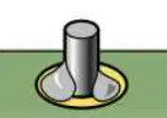
If your PCB solder joint looks like this, you applied...
too much solder.
too little solder.
too much heat.
too little heat.
If your PCB solder joint looks like this, you applied...
too much solder.
too little solder.
too much heat.
too little heat.

If your PCB solder joint looks like this, you applied...
too much solder.
too little solder.
too much heat.
too little heat.

If your PCB solder joint looks like this, you applied...
too much solder.
too little solder.
too much heat.
too little heat.

If you see this on your board, you know...
That you used the perfect solder amount
That you used too little solder
That you have an electrical short on the board.
That you have an electrical long on the board.
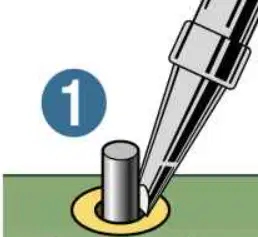
Approximately how long to you need to heat the components before applying solder?
2-3 seconds
10-15 seconds
20-30 seconds
2-3 minutes
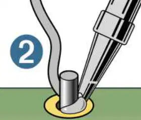
When applying solder, you push the tip of the wire...
into the PCB pad.
into the component wire.
into the soldering iron
into the point where the component and pad touch

