
 Worksheets
Lesson 1: Explain Cable Type and Connectors
Total questions: 124
Worksheet time: 10hrs 20mins
Define a personal computer in terms of user-handled components versus components that should not be exposed. Explain why this distinction matters for maintenance and safety.
Describe the typical functions of peripheral devices and provide at least three examples each for input and output.
List the internal components commonly housed in a PC system case and explain the role of the chassis in protecting them.
Explain why many PC cases use a tower form factor. Include orientation and placement considerations.
Outline the steps and precautions for opening a desktop tower case to perform maintenance. Mention side covers, fasteners, and documentation.
What functions does the front panel of a desktop case provide? Include controls, indicators, and access.
Explain the relationship between the rear panel and the power supply unit (PSU), including airflow considerations.
Describe the placement and purpose of the motherboard I/O cutout on the rear panel, and list common devices that connect there.
Explain the function of adapter card slots and the importance of covering unused slots with blanking plates.
Provide a maintenance checklist for ensuring proper airflow in a PC case, focusing on fans, slot covers, and obstructions.
Differentiate between external storage peripherals and fixed disks inside the case in terms of accessibility and handling.
Explain why front covers may require the side panel to be removed first, and discuss how this affects serviceability.
Define a peripheral device and explain how an I/O port and a peripheral cable enable it to function with a PC. Include two examples of peripheral devices and the matching port types they commonly use.
Differentiate between ports designed for a specific device type and ports that support a variety of devices. Provide one example for each and justify why the design differs.
Explain the typical physical placement of external ports on a PC and how this placement influences user accessibility and cable management.
Compare motherboard-integrated ports with ports provided via an expansion card. Discuss two technical or practical reasons to use each approach.
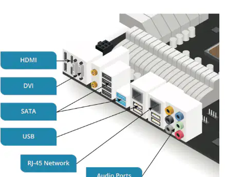
A PC rear panel shows labeled connectors: HDMI, DVI, SATA, USB, RJ-45 Network, and Audio Ports. For each, describe the main function and a common device or cable that uses it.
Define a hardware port and a bus interface. Describe the relationship between them during device communication.
Describe the role of the bus in data transfer to and from devices. Include how bus bandwidth relates to observable performance.
Explain what a connector is in the context of a peripheral cable. Discuss why connector shape or form factor must match the port.
Many bus interfaces support multiple connector form factors (for example, different USB types). Analyze two technical reasons vendors create multiple connector forms for the same interface, and note one risk this introduces.
Define keying in connectors and ports. Explain how asymmetric design or reversibility prevents incorrect insertion, giving one keyed and one reversible example.
When comparing bus interfaces, why is it important to use appropriate data units? Connect this to how computers process binary data.
Define bit and byte precisely. Explain why storage is measured in multiples of eight bits and how uppercase/lowercase B/b notation avoids ambiguity.
Given a network link specified at 100 Mbps, convert this rate to bits per second and bytes per second. State any assumptions clearly.
Explain the difference between Kb/s, Mb/s, and Gb/s versus KB/s, MB/s, and GB/s. Provide a realistic scenario where confusing these units would lead to a wrong performance estimate.
Show the multiplicative steps from kilobits to megabits to gigabits using the 1000-based progression described. Then evaluate how these units relate to practical transfer timings for a 1 GB file over a 100 Mb/s link.
Differentiate between a USB host controller and a USB device. Explain their roles on the bus and how multiple ports and devices are supported.
USB allows up to 127 devices per controller in theory. Analyze why many motherboards still implement multiple USB host controllers rather than relying on a single large tree.
Classify common peripherals into appropriate USB device classes and justify your choices for at least three examples.
Explain how USB standards have evolved from USB 3.2 Gen 1 to USB 3.2 Gen 2x2. Include naming, maximum signaling rates, and typical connector forms.
A laptop advertises one port as “USB 3.2 Gen 2x2 (20 Gbps)”. Describe what electrical/physical features must be present on the cable and port for this speed to be achievable.
Clarify the difference between a USB version (for example, USB 3.2 Gen 1) and a connector type (for example, USB Type‑C). Why are these often confused?
Describe the physical characteristics and typical use of a USB Type‑A connector, including insertion orientation and location in a system.
Contrast USB Type‑A and Type‑B connectors in terms of device roles and form factor. Provide a practical example for each.
Explain why USB introduced Mini and Micro connector variants. Identify scenarios where each would be preferred over full‑size Type‑B.
Discuss USB cable length considerations. What practical issues arise when exceeding recommended lengths, and what solutions can mitigate them?
Evaluate how USB power delivery affects device charging and peripherals that draw power from the bus. Include legacy 5 V behavior and modern negotiated power levels.
A desktop has four rear USB ports provided by one controller and two front‑panel ports wired to a second controller. Propose how you would distribute high‑bandwidth devices to optimize performance and explain why.
Given a requirement to connect a high‑speed external SSD at 10 Gbps to a thin laptop, choose an appropriate connector and cable type and justify compatibility concerns.
Explain how USB hubs extend connectivity. Discuss any trade‑offs introduced by placing multiple devices behind a single hub.
Design a troubleshooting checklist for a USB printer with a Type‑B port that intermittently disconnects when printing large files. Address cable, power, and controller factors.

For USB 2.0 devices, what are the typical maximum cable lengths recommended for Low Speed versus Full/High Speed connections? Explain why these limits exist.
A vendor markets a 10 m USB 2.0 cable. Discuss practical risks and conditions under which it might still work, and when you should avoid using it.
SuperSpeed USB (USB 3.x) has no official maximum cable length. Provide a recommended length and justify it based on signal integrity considerations.
Compare USB Type B Mini and Type B Micro connectors. Identify their typical device uses and a distinctive physical difference.

Explain how the USB bus supplies power alongside data. Include typical use cases and port types commonly used for charging.
You need to connect a high-speed external SSD via USB 3.x over 5 meters. Propose a reliable solution that respects cable length guidance and maintains performance.
A smartphone fails to charge when connected to a PC’s USB Type A port with a very long cable. Diagnose likely causes related to cable length and power delivery, and suggest remedies.
Early digital cameras used one connector type that is now largely obsolete. Name it, describe why it fell out of use, and state what replaced it for smaller devices.
A gaming PC outputs 3840×2160 at 120 Hz. Explain how resolution and refresh rate together affect the required video cable bandwidth, and why a dedicated video interface is preferred over USB for this scenario.
Differentiate between image resolution and refresh rate. Include how each is measured and give one example value for HD and one for 4K.
HDMI is widely used on consumer devices. Describe three features it supports that make it suitable for TVs, consoles, and Blu‑ray players.
Explain how variable refresh rate (VRR) in newer HDMI revisions benefits gaming when the frame rate of the video source changes.
Outline the purpose of HDCP in the HDMI ecosystem and how it relates to digital content protection between source and display.
Identify and describe the physical HDMI connector types (Type A, Type C, Type D). Include typical device use-cases and the role of the beveled/ keyed orientation.
Contrast HDMI’s licensing model with DisplayPort’s. Who developed each and what are the implications of royalty requirements for adoption?
Summarize DisplayPort capabilities that align with HDMI (e.g., resolution support, audio, and content protection). Highlight any notable distinctions for PC graphics use.
A workstation monitor supports DisplayPort DP++ and MiniDP. Explain what DP++ signifies and when you would choose MiniDP/mDP over full‑size connectors.
You must connect a laptop to a 4K monitor and carry audio on the same cable. Compare using HDMI versus DisplayPort, noting compatibility and feature support that ensures success.
Explain why video interfaces require high bandwidth and how bandwidth needs scale when moving from 1920×1200 at 60 Hz to 3840×2160 at 60 Hz and then to 120 Hz.
Provide a troubleshooting checklist for no‑signal issues when using HDMI or DisplayPort, focusing on connector type mismatches, orientation/keying, HDCP handshakes, and refresh rate/ resolution settings.
Compare Thunderbolt’s role as a display interface with HDMI and DisplayPort, and explain how Thunderbolt also functions as a general peripheral interface similar to USB.
Explain how Thunderbolt versions 1 and 2 use the Mini DisplayPort (MiniDP) physical connector and describe the practical implication for connecting a monitor with a DisplayPort port to a computer that has Thunderbolt.
A technician sees a lightning bolt/flash icon next to a MiniDP-sized port. Identify the interface and explain why the icon matters.
Analyze the data rate capability of Thunderbolt version 2 and discuss suitable use cases that benefit from this bandwidth.
Describe daisy-chaining with Thunderbolt and outline a scenario where multiple monitors connect through a single port.
Discuss the growing platform support for Thunderbolt beyond Apple and what this implies for cross-platform peripherals.
Explain the proprietary nature of Apple’s Lightning interface and identify the devices where the Lightning port is found.
Evaluate the usability impact of the Lightning connector’s reversibility compared to older USB-A or micro-USB connectors.
A student needs to transfer photos from an iPhone to a Windows PC. Specify the adapter cable types that enable this connection and explain why they are needed.
Contrast Thunderbolt and Lightning in terms of connector standardization, typical usage domains, and interoperability with non-Apple systems.
Explain how Thunderbolt’s compatibility with DisplayPort affects monitor deployment choices for laptops and desktops equipped with Thunderbolt ports.
Provide guidance for distinguishing between a MiniDP port and a Thunderbolt port when the physical connector looks identical.
Identify the role of Serial Advanced Technology Attachment (SATA) in desktop PCs and explain why each SATA host adapter port supports a single device.
Differentiate the SATA data connector from the SATA power connector in terms of pin count and function.
A technician is building a PC and routes a 7‑pin cable from the motherboard to a hard drive. The drive does not spin up. Diagnose the likely cause and the corrective action.
Compare throughput across SATA revisions 1, 2, and 3 and state their nominal transfer rates.
Explain the typical maximum cable length for internal SATA and why excessively long internal cables are discouraged.
Describe the use case for Molex power connectors in modern PCs and why they still appear on PSUs.
Outline the physical characteristics and pin count of a typical Molex connector used for PC power.
Map Molex wire color coding to DC voltage rails and ground.
Why are internal storage device data cables described as unpowered, and what implication does this have when installing drives?
Evaluate the advantages and limitations of eSATA compared to USB for external storage.
State the required cable type to connect a peripheral to an external eSATA port and why an internal SATA cable is unsuitable.
Explain what eSATAp is and how it differs from standard eSATA.
Given a drive requiring 12 V for the motor and 5 V for logic, select appropriate PSU connector(s) and justify your choice.
A system has a SATA revision 2 motherboard port and a SATA revision 3 SSD. Predict the negotiated link speed and explain.
You need to attach an external 2.5‑inch portable drive without an external power brick. Which interface is more practical and why?
Explain how the CPU and RAM collaborate to execute software instructions, and why RAM is described as nonpersistent. Include what happens to data in RAM when the PC powers off.
Describe the role of binary code in processing software and data on a PC. Why are ones and zeros suitable for digital computation at the hardware level?
A system is running multiple applications but begins to slow down when additional programs are opened. Analyze how CPU instruction storage limits and system memory affect this behavior.
Differentiate between nonpersistent storage (RAM) and mass storage devices in terms of data retention and typical use cases during normal PC operation.
Explain how motherboard bus interfaces enable communication among components. Include how instructions and data move electrically across buses.
Define the system clock on a motherboard and analyze how it synchronizes component operations and provides timing for the CPU.
Clock speeds are measured in MHz or GHz. Explain the concept of clock multipliers and how they allow different buses to operate at different frequencies from a single timing source.
A technician observes that the memory bus is operating at a lower frequency than the CPU core. Explain how clock generation and multipliers can produce this configuration and why it might be desirable.
Evaluate how the choice of motherboard influences system speed and the upgrade options for devices and adapter cards. Provide examples of constraints a motherboard might impose.
List several major motherboard manufacturers and discuss one practical reason a technician might choose one brand over another for a specific build.
Explain why each motherboard supports only a particular range of CPUs. Include socket type, chipset, and electrical or firmware compatibility in your explanation.
Identify the principal PC CPU manufacturers and compare typical considerations when selecting between them for a desktop system (such as performance, platform features, and compatibility).
List the exact steps you should take to ensure electrical safety before opening a PC case to install or troubleshoot a motherboard. Explain why each step is necessary.
Explain electrostatic discharge (ESD): what it is, why it occurs when working on PCs, and how it can damage components.
Identify at least four PC components that are vulnerable to ESD and describe the potential consequences of improper handling for each.
Provide a detailed procedure for safely handling and installing a CPU and RAM module to minimize ESD risk, including required tools and contact points.
Describe how and why to drain residual charge from a PC after unplugging it. Include the mechanism by which pressing the power button helps.
Argue whether it is appropriate for a technician to disassemble a PC power supply during field service. Support your position with safety reasoning.
Design a brief checklist a grade‑13 technician can use during motherboard upgrades to ensure personal safety and component protection from ESD.
A student touches a graphics adapter card after walking on a carpet without an anti‑ESD strap and feels a small shock. Diagnose what happened and outline immediate and future preventative actions.
Explain how a motherboard’s chipset influences CPU compatibility, RAM capacity, and onboard interface support. Include why chipset upgrades are not a typical field upgrade.
Describe the relationship between the CPU socket, heat sink, and fan during and after CPU installation. Why is proper cooling critical?
Most PC CPUs are produced by Intel and AMD and use different socket designs. Analyze the implications of this for selecting a replacement motherboard for an existing CPU.
A technician must determine whether a motherboard can accept DDR5 modules. Outline the steps and evidence on the board that would confirm compatibility without powering on the system.
Define RAM volatility and discuss its practical consequences for saving work and system behavior during a sudden power loss.
Differentiate the roles of RAM and persistent storage during program execution. Provide an example of how data flows between them and the CPU.
Explain why a DIMM form factor is tied to a particular DDR generation and what physical or electrical features prevent cross-generation installation.
Given a motherboard with four color‑coded DIMM slots near the CPU socket, explain how numbering and color coding guide installation for optimal performance.
Describe how controllers within the chipset manage data transfer between CPU and devices such as video, sound, storage, and networking. Include an example path for a disk read.
A system will be upgraded from 16 GB DDR4 to 64 GB DDR4. Discuss the factors that determine whether this is feasible on the existing motherboard.
Explain why new motherboards are generally released to support the latest CPU models and how rapid CPU technology changes limit backward compatibility.
Outline safe procedures for installing a CPU into its socket, including alignment, locking, thermal paste, and cooler attachment.
Compare DDR3, DDR4, and DDR5 at a high level in terms of generational improvements and typical motherboard support considerations.
A motherboard lacks native support for a specific interface required by a new adapter. Evaluate when using an adapter card is appropriate and any performance or compatibility trade‑offs.
Explain how the number of physical memory slots and the capabilities of the memory controller together set the upper limit of system RAM. Provide a brief example calculation.

