
 Worksheets
Exercise 1: Cantilever Beam Tapering
Total questions: 19
Worksheet time: 10mins

Why are cantilever beams for the roof shown often tapered thicker near the support and thinner toward the free end?
Because wind pressure is uniformly higher at the free end
Because bending moment and shear are highest near the support
So the beam vibrates more under pedestrian loads
To make fabrication easier with constant thickness plates
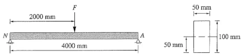
A 4 m simply supported beam has a rectangular cross-section of 100 mm by 50 mm. The second moment of area is 4.17×10^6 mm^4, and the maximum allowable bending stress at the bottom edge is 42 MPa. A point load F is applied at the midspan. What is the maximum permissible value of F ?
3.5 MN
875.7 N
87.6 kN
1751.4 N

A cantilever beam must withstand a maximum bending moment of 750 N·m. Five candidate sections have the following Ix (m4) and ymax (m): A: Ix= 1.688×10⁻⁶ , ymax=0.050; B: Ix= 1.412×10⁻⁶ , ymax=0.040; C: Ix= 2.459×10⁻⁶ , ymax=0.065; D: Ix= 0.916×10⁻⁶ , ymax=0.035; E: Ix= 1.269×10⁻⁶ , ymax=0.040. Select the section that minimizes maximum bending stress σmax=IxM⋅ymax , and estimate σmax for that section.
Section A, about 22.2 MPa
Section C, about 19.8 MPa
Section D, about 28.7 MPa
Section E, about 23.6 MPa
Section B, about 21.3 MPa
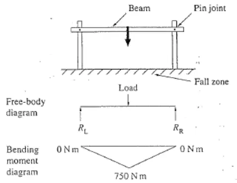
A simply supported beam spans 3.0 m between two pinned supports. A point load is applied at midspan, producing a peak bending moment of 750 N·m at the center and zero at the supports. What is the reaction force at each support?
1000 N at each support
500 N at each support
750 N at each support
375 N at each support
250 N at each support
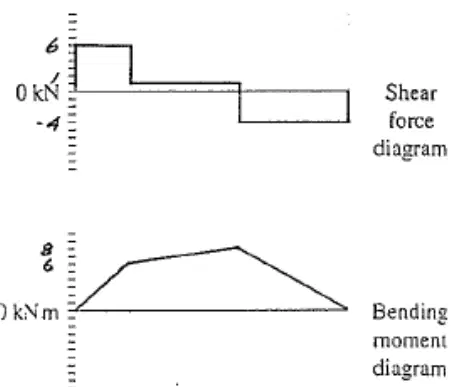
A simply supported cross-beam carries four concentrated downward loads: 6 kN at 0 m, 5 kN at 1 m, 5 kN at 3 m, and 4 kN at 5 m from the left end. On the shear force diagram, what happens to the shear value immediately after passing the 1 m point?
It drops by 5 kN step downward
It rises by 5 kN step upward
It remains constant across the section
It changes linearly between supports
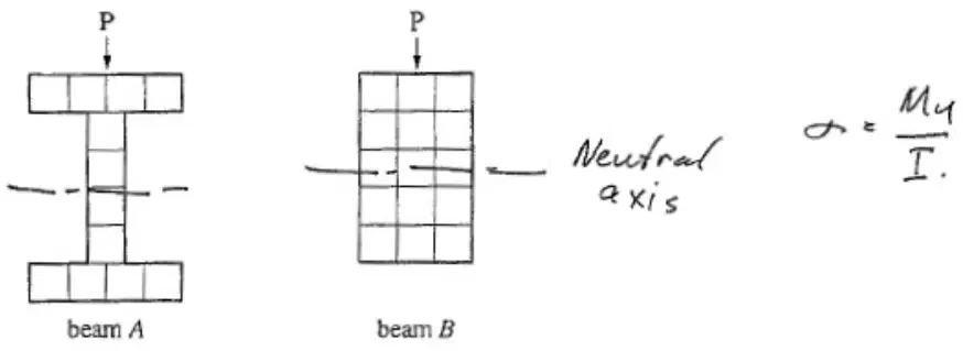
Two beams A and B carry the same bending moment M. Beam A is an I-section and Beam B is a solid rectangle of the same overall depth. Which statement best explains why the maximum bending stress is lower in beam A? Use σ = My/I.
Beam A has a larger y and similar I
Beam A has a smaller y and larger I
Beam A has the same y and same I
Beam A has the same y but smaller I
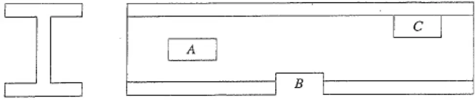
A rectangular hole must be cut in a simply supported steel beam to pass a service pipe. Three possible positions are shown: A at the mid‑depth near the center web, B as a recess at the bottom edge, and C near the top edge. Which location minimizes the reduction in bending strength?
Location C positioned near the top edge
Location B recessed at the bottom edge
Location A at the neutral axis mid‑depth
Any location gives the same strength loss
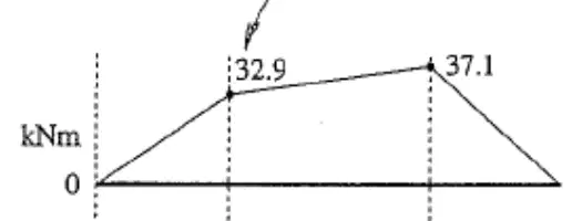
A simply supported beam carries two downward point loads: 8.0 kN at 3.5 m from the left support and 12.0 kN at 6.5 m from the left support. The reactions are 9.4 kN at the left support and 10.6 kN at the right support. Which bending moment diagram best represents the beam, given that the bending moment is Varignon-consistent, starts and ends at zero, increases linearly between loads, and shows maximum positive ordinates near the loads of approximately 32.9 kNm and 37.1 kNm?
Inverted V with minima at 37.1 kNm and 32.9 kNm
Entirely negative with ordinates 28.0 kNm and 42.0 kNm
Zero at supports, peak 28.0 kNm then negative 42.0 kNm
Triangular rise to 32.9 kNm then to 37.1 kNm
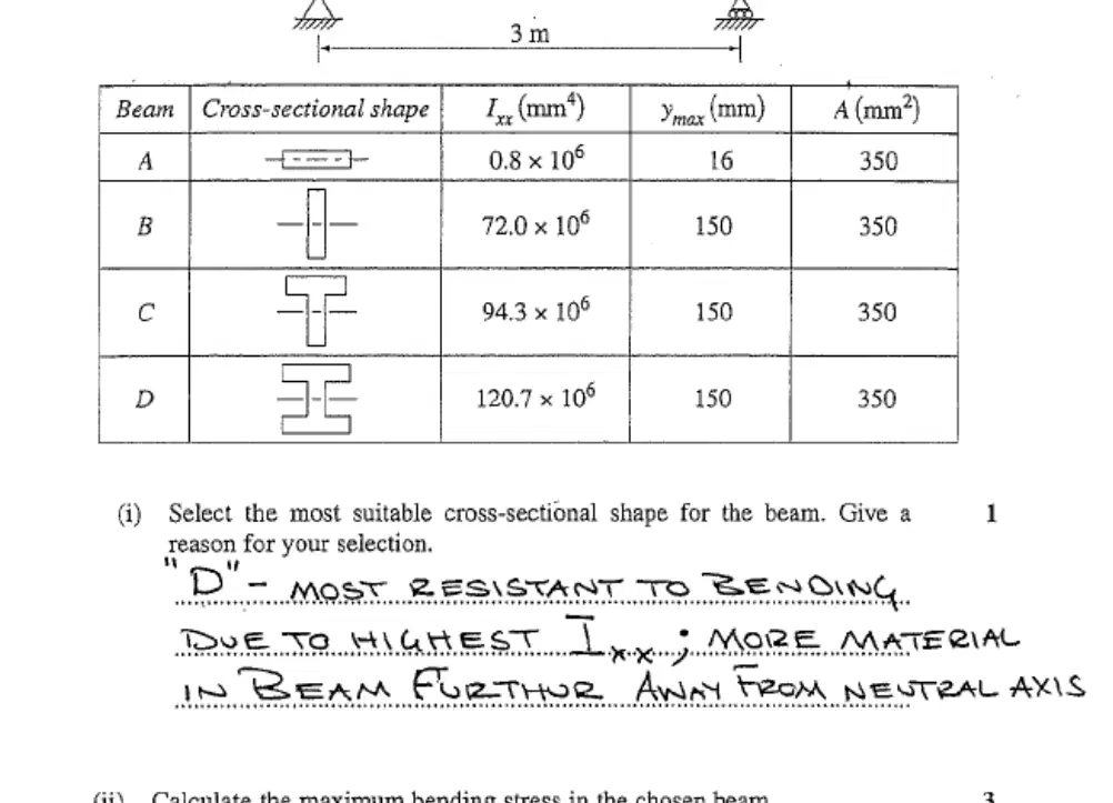
A simply supported 3 m beam carries a 20 kN point load at midspan. Four candidate cross-sections have the same area A = 350 mm2 and ymax = 150 mm, but different second moments of area: A: 0.8×106mm4 , B: 72.0×106mm4 , C: 94.3×106mm4 , D: 120.7×106mm4 . Which section minimizes the maximum bending stress?
Section D with highest I_x value
Section B with moderate I_x value
Section A with lowest I_x value
Section C with higher I_x value
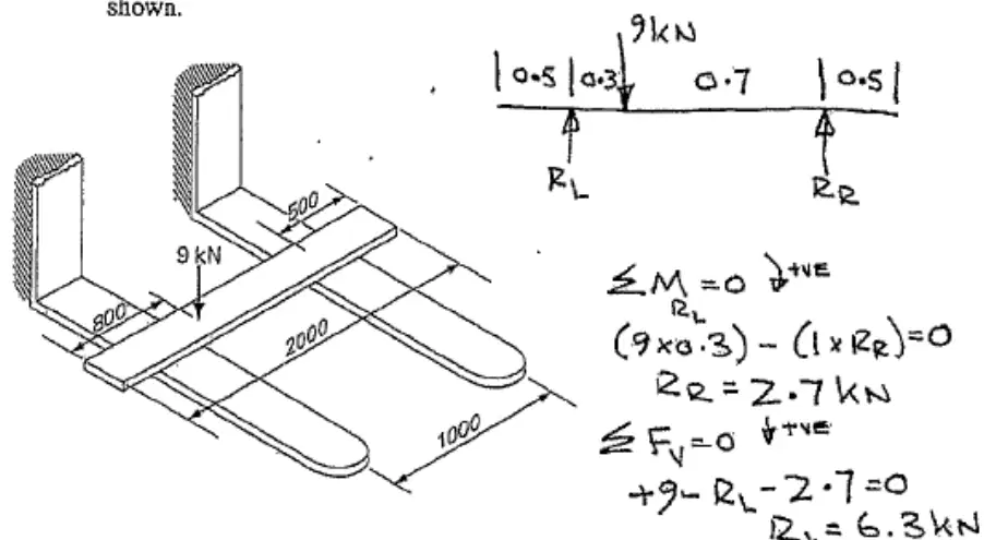
A 2 m forklift beam is simply supported with reactions at the left and right forks. A 9 kN point load acts 0.8 m from the left support and 1.2 m from the right support. What is the vertical reaction at the right support?
4.5 kN upward
6.3 kN upward
2.7 kN upward
9.0 kN upward
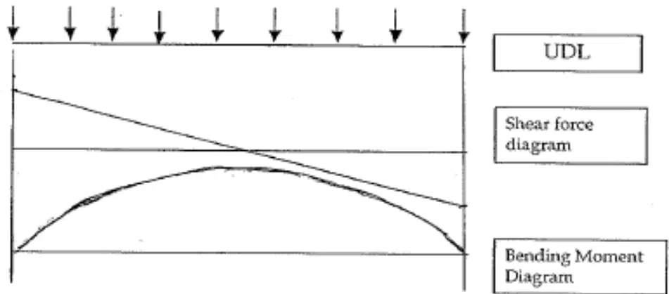
A simply supported beam carries a uniformly distributed load (including self‑weight) over its entire span. Which statement best describes the typical shapes of the shear force and bending moment diagrams?
Shear force is linear; bending moment is parabolic downward
Shear force is sinusoidal; bending moment is cubic upward
Shear force is parabolic; bending moment is linear downward
Shear force is constant; bending moment is triangular upward
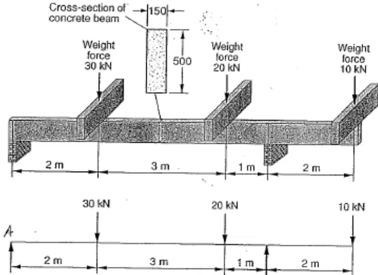
A simply supported concrete beam carries three point loads: 30 kN at 2 m from the left support, 20 kN at 5 m from the left support, and 10 kN at 8 m from the left support. What is the reaction at the right support?
30 kN upward
40 kN upward
15 kN upward
20 kN upward
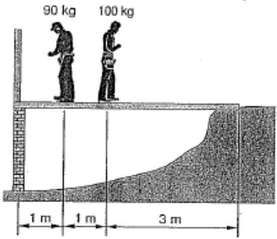
A simply supported plank beam spans 5 m and carries two point loads representing workmen: 900 N at 1 m from the left support and 1000 N at 2 m from the left support. What is the vertical reaction at the right support RB?
580 N upward reaction at the right support
500 N upward reaction at the right support
740 N upward reaction at the right support
420 N upward reaction at the right support
Which statement best describes shear force and bending moments in a beam?
They are equal to support reactions at all times
They are internal reactions to applied external loads
They are unrelated when bending moment is zero anywhere
They remain constant along the entire beam length
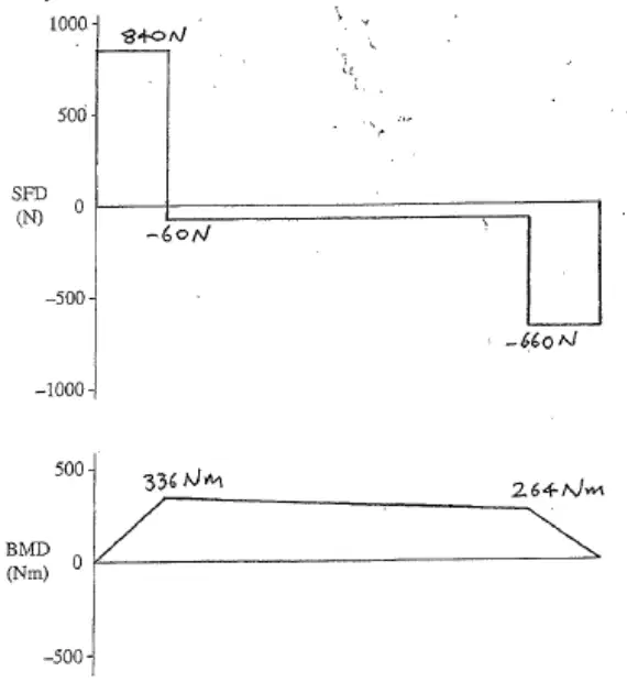
A simply supported 2 m cross beam carries two point loads: 900 N at 0.4 m from the left support and 600 N at 1.6 m from the left support. Ignoring self-weight, which sketch best represents the qualitative shape of the bending moment diagram (BMD)?
A parabolic BMD peaking under the heavier load
A triangular BMD rising linearly from Amal to right
A rectangular BMD constant between the two loads
A piecewise linear BMD with peaks under each point load
When a uniformly distributed load (UDL) is added to a simply supported beam previously analyzed with only point loads, how does the shape of the bending moment diagram (BMD) change between supports?
Triangular segments between supports
Curved parabolic segments between supports
Piecewise constant segments between supports
Straight linear segments between supports
A beam cross-section has second moment of area I = 14×10−6m4 . At a section where the bending moment is M = 336N⋅m and the distance to the outer fiber is y = 0.075m , estimate the maximum bending stress using σ=IMy .
18 MPa approximately
0.18 MPa approximately
0.018 MPa approximately
1.8 MPa approximately
A simply supported 16 m beam carries two equal point loads of 5 kN located 5 m from the left support and 5 m from the right support. What is the reaction at each support?
2.5 kN upward at each support
5 kN upward at each support
10 kN upward at each support
5 kN downward at each support
For the same 16 m beam with two 5 kN point loads placed symmetrically as described, what is the maximum bending moment in the beam?
20.0 kN·m at a support
25.0 kN·m near each load
12.5 kN·m at midspan
40.0 kN·m at midspan

