
 Worksheets
Power Supplies and Amplifiers B1b-10
Total questions: 52
Worksheet time: 27mins
Why is the AC power source only connected to the primary of the transformer?
a) Because the impedance of the transformer is only sufficient in the primary to handle the high voltage.
b) Because the grounded portion of the power source is not safe for the secondary-connected circuits.
c) To isolate the electrical circuits from the power source.
d) To prevent arc-flash incidents.
What is the first concern when selecting a transformer for a power supply circuit?
a) The primary power rating (the voltage of the power source).
b) The physical size and shape of the transformer.
c) The number of turns in the secondary coil
d) The reactance of the primary coil compared to the reactance of the secondary coil.
The volt-ampere rating of a power transformer tells someone:
a) The minimum current rating when choosing an overcurrent protection device.
b) The ratio of the input to output voltage and current.
c) If the transformer operates with single-phase power or three-phase power.
d) Essentially, the amount of power that can be delivered to the secondary of the transformer.
Rectifier Circuits
What is the purpose of a rectifier circuit in a power supply?
a) It converts the incoming DC voltage to an AC voltage.
b) It converts the incoming AC voltage to a DC voltage.
c) It regulates the output voltage when there are changes in the input voltage.
d) It changes the input voltage to a more suitable voltage for the load (either increases or decreases the input voltage).
What does the term “ripple frequency” mean when talking about the output of a rectifier?
a) It is the maximum input frequency the power source can handle.
b) It is the frequency of the fundamental harmonic created by the power source.
c) It is the frequency of the pulses leaving the rectifier circuit. It depends on whether the rectifier is full-wave or half-wave.
d) It is the frequency created by the interaction of the rectifier with the transformer primary.
Which of the following is NOT true of a half-wave rectifier?
a) The diode prevents current from flowing in both directions (AC).
b) There are two diodes connected in series with the load.
c) The current in the circuit flows in one direction only.
d) There is one diode is connected in series with the load.
How many diodes does a full-wave rectifier have?
a) One if it is a standard full-wave rectifier, and two if it is a full-wave bridge rectifier.
b) One diode for a low current output, or two in parallel for a high current output.
c) Two if it is a standard full-wave rectifier, and four if it is a full-wave bridge rectifier.
d) Two diodes in series for a low current output, or two in parallel for a high current output.
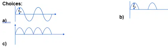
What does the waveform of a half-wave rectifier look like?
(a)
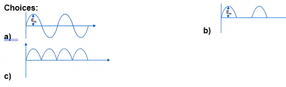
What does the waveform of a full-wave rectifier look like?
(a)
With a transformer using a center tapped secondary, what is true about the voltages at each end of the transformer secondary?
a) They are 90 degrees out of phase with each other.
b) They are 180 degrees out of phase of each other.
c) They are considered “split phase.”
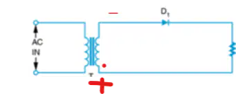
For the rectifier shown, which diode(s) conduct (have current flow through them when the input waveform gives the transformer secondary the polarities shown?
a) D1
b) The diode is not conducting.
What is the advantage of a full-wave rectifier when compared with a half-wave rectifier?
a) The full-wave rectifier is more efficient than the half-wave rectifier.
b) The full-wave rectifier operates on both alternations of the sine wave.
c) The higher ripple frequency of the full-wave rectifier is easier to filter.
d) All of the above are correct.

For the rectifier shown, which diode(s) conduct (have current flow through them when the input waveform gives the transformer secondary the polarities shown?
a) D1
b) D2
c) None of the diodes are conducting.
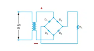
For the rectifier shown, which diode(s) conduct (have current flow through them when the input waveform gives the transformer secondary the polarities shown?
D1
D2
NONE
D1 AND D3
D2 AND D4
Filter Circuits
Why is a filter circuit needed for the output of a rectifier?
a) The output of a rectifier generally has a varying voltage level, and the filter circuit helps maintain the same voltage over time.
b) The output of the rectifier is a pulsating DC voltage that is not suitable for most electronic circuits.
c) The output of a rectifier is regularly subjected to voltage spikes and transients.
d) To reduce the size of the transformer that is needed to power the circuit.
Which of the following statements best describe how a capacitor filter circuit works?
a) When current first begins to flow in a rectifier circuit, the capacitor starts to discharge. After 90 degrees of the input signal, the capacitor has reached zero voltage, and is then recharged by the opposite polarity of alternation as it increases from zero volts.
b) When current flows in a rectifier circuit, the capacitor charges. After 90 degrees of the input signal, the capacitor is fully charged. When the input signal starts to drop in the negative direction, the capacitor discharges through the load, making up for the drop in voltage at the power source.
What is the purpose of the filter capacitor in a power supply circuit?
a) To smooth out the pulsating DC voltage from the rectifier.
b) To protect against voltage spikes and transients.
c) To decrease the ripple frequency.
d) To help turn AC into DC.
When a larger capacitor is used for a filter circuit, which of the following will occur as a result?
a) The input current will increase.
b) The ripple frequency will increase.
c) The diode current will increase.
d) The overall output voltage is raised (increased).
A full-wave rectifier used with a capacitor filter will result in a higher output voltage (higher average voltage) than a half-wave rectifier with a capacitor filter would create.
a) This statement is true.
b) This statement is false.
Voltage Regulators
20. What are the two factors that can cause the output voltage of a power supply to vary? (You will choose two answers from the choices below.)
a) The input voltage to the power supply can vary.
b) The load resistance can vary, resulting in a change in current demand.
c) The secondary impedance of the transformer can vary.
d) The transformer’s turns ratio can vary depending on the actions of the voltage regulator.
Which of the following best describes the purpose of the voltage regulator in a power supply circuit?
a) It maintains the same amount of current regardless of the amount of output voltage created.
b) It regulates the output voltage by changing the amount of voltage coming into the power supply.
c) It changes the impedance of the load to compensate for changes in input voltage.
d) It allows the power supply to produce the same output voltage regardless of changes to the load and/or the input voltage.
Voltage Multipliers
Which of the following best describes a voltage multiplier circuit?
a) They produce greater voltages by increasing the transformer turns ratio.
b) They are able to produce a higher DC voltage without a step-up transformer.
c) They are able to take a lower-voltage DC voltage and increase it without the use of diodes.
d) They are able to increase a lower AC voltage to become a higher AC voltage.
Which of the following best describes the voltage of a capacitor that has a pulsating DC voltage signal applied to it (such as the output of a half-wave or full-wave rectifier)?
a) It charges up to exactly one-half of the voltage of the signal (50% of the peak voltage).
b) It charges up to the average voltage of the signal (approximately 63% of the peak voltage).
c) It charges up to the RMS voltage of the signal (approximately 70% of the peak voltage).
d) It charges up to the peak voltage of the signal.
Circuit Protection Devices
How does a “crowbar” circuit operate when there is an over-voltage condition?
a) The SCR is in series with the load and turns off at a predetermined voltage level, reducing the current to zero.
b) The SCR is in parallel with the load and turns on at a predetermined voltage level, placing a short across the load and blowing the power supply fuse.
c) The SCR is in series with the fuse. When the SCR is activated, the fuse blows.
d) The SCR is connected to a relay coil. When the SCR turns on, so does the relay, creating a short circuit that blows the power supply fuse.
When exposed to a high transient voltage, what does an MOV or varistor do?
a) It clamps the voltage to a safe level, absorbing the excess energy.
b) It melts like the element in a fuse, stopping the flow of current.
c) It reduces its internal resistance to a very low value, blowing the power supply fuse.
d) It creates CEMF (counter electromotive force) that subtracts from the applied voltage.
The two classifications of fuses listed in the textbook is the “normal” fuse and the:
a) Solid state circuit fuse
b) Inductive fuse
c) Short fuse
d) Slow-blow fuse
Amplifier Configurations
The common-emitter amplifier is the most common BJT transistor amplifier configuration. It is so named because:
a) The emitter is common to both the input and output circuit.
b) The emitter is the common input location.
c) The emitter is attached to earth ground in almost every circuit configuration.
d) The emitter, collector, and base all share a single, common power source.
What is the phase relationship between the input and output waveforms for a common-emitter amplifier?
a) The voltage waveform of the output is lagging the current waveform of the input by 90 degrees.
b) The input and output waveform have no phase shift (they are in phase with each other).
c) The output waveform is 90 degrees out of phase with the input waveform.
d) The output waveform is 180 degrees out of phase with the input waveform.
Amplifier Biasing
How should the base-emitter junction be connected in a BJT amplifier?
a) Forward biased
b) Reverse biased
How should the base-collector junction be connected in a BJT amplifier?
a) Forward biased
b) Reverse biased
Which of the following is true about the voltage across resistor RL (in series with the collector) and the voltage across the transistor’s collector-emitter junction (the voltage between the collector and emitter)?
a) They should be identical.
b) They should add up to the voltage measured at the base.
c) They should add up to the total voltage applied.
d) They divide in an inversely proportional way.
What is the purpose of the resistor RB?
a) It controls the amount of current flowing out of the base.
b) Most of the voltage from the source is dropped across it.
c) It allows a small amount of voltage drop across the transistor’s base-to-emitter junction, providing the proper forward bias.
d) All of the above are correct.
Where is the input signal applied to the amplifier circuit?
a) Between the transistor’s base and emitter.
b) Between the input terminal and ground.
c) Both of the above answers are correct.
d) None of the above answers are correct.
Looking over the input versus output waveforms, what is true about a “Class AB” amplifier?
a) Less than half of the input waveform (less than 180 degrees) is reproduced at the output.
b) Exactly half of the input waveform (180 degrees) is reproduced at the output.
c) A little less than all of the input waveform (greater than 180 degrees, but less than 360 degrees) is reproduced at the output.
d) The entire input waveform (all 360 degrees) is reproduced at the output.
Looking over the input versus output waveforms, what is true about a “Class C” amplifier?
a) Less than half of the input waveform (less than 180 degrees) is reproduced at the output.
b) Exactly half of the input waveform (180 degrees) is reproduced at the output.
c) A little less than all of the input waveform (greater than 180 degrees, but less than 360 degrees) is reproduced at the output.
d) The entire input waveform (all 360 degrees) is reproduced at the output.
Looking over the input versus output waveforms, what is true about a “Class A” amplifier?
a) Less than half of the input waveform (less than 180 degrees) is reproduced at the output.
b) Exactly half of the input waveform (180 degrees) is reproduced at the output.
c) A little less than all of the input waveform (greater than 180 degrees, but less than 360 degrees) is reproduced at the output.
d) The entire input waveform (all 360 degrees) is reproduced at the output.
Looking over the input versus output waveforms, what is true about a “Class B” amplifier?
a) Less than half of the input waveform (less than 180 degrees) is reproduced at the output.
b) Exactly half of the input waveform (180 degrees) is reproduced at the output.
c) A little less than all of the input waveform (greater than 180 degrees, but less than 360 degrees) is reproduced at the output.
d) The entire input waveform (all 360 degrees) is reproduced at the output.
Amplifier Coupling
Why is a coupling technique used between transistor amplifier circuits?
a) It prevents oscillation and undesired signal feedback.
b) It creates the bias voltage present between the base-emitter junction.
c) It converts the AC signal to a changing DC voltage.
d) It prevents one of the amplifier’s bias voltage from affecting the operation of the second amplifier.
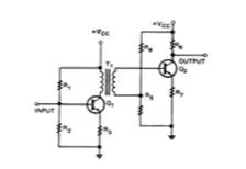
Which of the following coupling methods is shown by the schematic at the right?
a) Resistance-capacitance coupling
b) Impedance coupling
c) Transformer coupling
d) Direct coupling
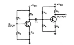
Which of the following coupling methods is shown by the schematic at the right?
a) Resistance-capacitance coupling
b) Impedance coupling
c) Transformer coupling
d) Direct coupling

Which of the following coupling methods is shown by the schematic at the right?
a) Resistance-capacitance coupling
b) impedance coupling
c) Transformer coupling
d) direct coupling
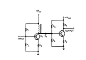
42. Which of the following coupling methods is shown by the schematic at the right?
a) Resistance-capacitance coupling
b) Impedance coupling
c) Transformer coupling
d) Direct coupling
Operational Amplifiers
Which of the following is a characteristic of an op-amp?
a) They can amplify both AC and DC signals.
b) They usually have two input connections.
c) They typically have a high gain in the range of 20,000 to 100,000 times the input.
d) All of the above are correct.
The amplifier input that is indicated by a plus sign (“+”) is the:
a) Positive power supply connection.
b) Negative power supply connection.
c) Non-inverting input.
d) Inverting input.
The amplifier input that is indicated by a minus sign (“-”) is the:
a) Positive power supply connection.
b) Negative power supply connection.
c) Non-inverting input.
d) Inverting input.
Which of the following is true about the op-amp power supply?
a) Generally, op-amps are designed to be powered by a dual voltage supply in the range of ±5V to ±15V
b) Generally, op-amps are designed to be powered by a dual voltage supply in the range of ±10V to ±25V
c) Generally, op-amps are designed to be powered by a single voltage supply of 3.5V, 5V, or 12V.
d) Generally, op-amps are designed to be powered by a single voltage supply in the range of 5V to 15V.
What is the difference between a “closed loop” mode and an “open loop” mode?
a) Open loop mode is where feedback is used to control the op-amp’s gain, and closed loop mode does not.
b) Closed loop mode is where feedback is used to control the op-amp’s gain, and open loop mode does not.
What is the purpose of the “feedback” signal in an op-amp circuit?
a) The feedback signal opposes the input signal.
b) The feedback signal adds to the input signal.
c) The feedback signal allows the circuit to operate with less power draw.
When an op-amp is operated as an “inverting” amplifier, how does the output signal compare with the input signal?
a) The voltage waveform of the output is lagging the current waveform of the input by 90 degrees.
b) The input and output waveform have no phase shift (they are in phase with each other).
c) The output waveform is 90 degrees out of phase with the input waveform.
d) The output waveform is 180 degrees out of phase with the input waveform.
When an op-amp is operated as a “non-inverting” amplifier, how does the output signal compare with the input signal?
a) The voltage waveform of the output is lagging the current waveform of the input by 90 degrees.
b) The input and output waveform have no phase shift (they are in phase with each other).
c) The output waveform is 90 degrees out of phase with the input waveform.
d) The output waveform is 180 degrees out of phase with the input waveform.
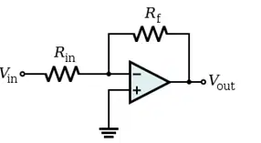
Which of the following operational amplifier circuits is represented by the schematic at the right?
a) Inverting amplifier
b) Non-inverting amplifier
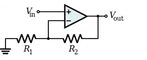
Which of the following operational amplifier circuits is represented by the schematic at the right?
a) Inverting amplifier
b) Non-inverting amplifier

