
 Worksheets
U14_PPS12_ELECTRICAL_CH12
Total questions: 40
Worksheet time: 20mins
According to the chapter’s learning outcome list for Unit 3, identify the need described regarding protective devices in electrical installations.
They are optional in low-voltage installations only
They are necessary to reduce risks such as shock, fire, overload and short circuit
They should be used only when RCDs are unavailable
They are primarily for improving energy efficiency
From the margin definitions, select the term that matches: the conductive mass of the earth whose electrical potential is taken as zero.
Earthing
Earth
Bonding
Extraneous conductive parts
From the margin definitions, select the term that matches: the act of connecting the exposed conductive parts of an installation to the main protective earthing terminal of the installation.
Earthing
Bonding
Basic protection
Fault protection
From the margin definitions, select the term that matches: a protective conductor providing equipotential bonding.
Circuit protective conductor (CPC)
Bonding conductor
Exposed conductive parts
Shock protection
From the margin definitions, select the term that matches: the linking together of the exposed or extraneous metal parts of an electrical installation.
Bonding
Earthing
Basic protection
Electrical separation
From the margin definitions, select the term that matches: a protective conductor connecting exposed conductive parts of equipment to the main earthing terminal; this is the green and yellow insulated conductor in twin and earth cable.
Circuit protective conductor (CPC)
Bonding conductor
Earthing electrode
Neutral conductor
From the margin definitions, select the term that matches: the metalwork of an electrical appliance or the trunking and conduit of an electrical system which can be touched because they are not normally live, but which may become live under fault conditions.
Exposed conductive parts
Extraneous conductive parts
Basic protection
Shock protection
From the margin definitions, select the term that matches: the structural steelwork of a building and other service pipes such as gas, water, radiators and sinks, which do not form a part of the electrical installation but may introduce a potential to the electrical installation.
Exposed conductive parts
Extraneous conductive parts
Bonding
Fault protection
From the margin definitions, select the term that matches: protection from electric shock provided by the insulation of live parts in accordance with Section 416 of the IEE Regulations.
Shock protection
Basic protection
Fault protection
Protective equipotential bonding
From the margin definitions, select the term that matches: protection provided by protective equipotential bonding and automatic disconnection of the supply (by a fuse or miniature circuit breaker, MCB) in accordance with IEE Regulations 411.3 to 6.
Basic protection
Fault protection
Electrical separation
Non-conducting location
According to the definition note, protective equipotential bonding is equipotential bonding carried out for safety purposes as shown elsewhere in the book. Choose the statement that best reflects this purpose.
It equalizes potentials between exposed metalwork to minimize touch voltages during faults
It increases circuit operating voltage to improve efficiency
It provides decorative insulation on metal surfaces
It disconnects supply without any earthing path
The text on basic protection explains that direct contact with live parts is prevented primarily by insulation suitable for the circumstances and stresses. What is identified as the primary method of protection against direct contact at normal mains voltage?
Barriers only
Insulation of live parts
Automatic disconnection of supply
Double pole switching
Based on the discussion of wet skin or wet surfaces, why are special considerations required in bathroom installations?
Wet conditions decrease skin resistance, increasing shock current for a given voltage
Wet conditions increase skin resistance, decreasing shock current
Bathrooms have no exposed metalwork
Bathrooms do not require earthing
According to the section on fault protection, which of the following are recognized methods of protection against indirect contact with exposed conductive parts? Select all that apply.
Protective equipotential bonding coupled with automatic disconnection of the supply
Use of Class II (double insulated) equipment
Provision of a non-conducting location
Use of earth-free equipotential bonding
Electrical separation
Which methods of protection are stated as limited to special situations under effective supervision of trained personnel?
Protective equipotential bonding with automatic disconnection and Class II equipment
Non-conducting location and earth-free equipotential bonding
Electrical separation and Class II equipment
Automatic disconnection and basic insulation
In the explanation of the most universally used method in the United Kingdom, what combination is identified?
Electrical separation only
Class II equipment only
Protective equipotential bonding with automatic disconnection of the supply
Non-conducting location with barriers
For final circuits not exceeding 32 A , what maximum disconnection time is stated by IEE Regulation 411.3.2?
0.1 s
0.4 s
1.0 s
4.0 s
The earth fault loop impedance of the circuit (Zs) must be less than values given in standards to achieve the required disconnection times. Which parameter is identified as needing to be less than the tabulated values?
Prospective short-circuit current (PSC)
Earth fault loop impedance (Zs)
Load power factor
Supply frequency
According to IEE Regulation 411.3.3, what additional protection is required for socket outlets rated not exceeding 20 A for use by ordinary people outside buildings when the earth return path may be unreliable?
An RCD with a rated operating current not more than 30 mA
An MCB rated at 32 A
A fuse rated at 13 A
A surge protective device
What does an RCD do, according to the description provided?
Compares the currents in line and neutral and disconnects the circuit when an imbalance indicating earth fault occurs
Measures voltage and disconnects at overvoltage only
Balances the load to improve power factor
Provides only mechanical isolation without sensing current
In a 10 mm PVC sheathed mineral insulated (MI) copper cable connected to a 400 V supply with short-circuit path impedance 0.1 Ω, calculate the fault current using I = V ⁄ Z.
1000 A
2000 A
4000 A
8000 A
For PVC sheathed MI copper cables with k = 115 and cross-sectional area S = 10 mm², subjected to a short-circuit current of 4000 A, determine the maximum permissible disconnection time using the relation t=I2k2S2 .
8.266 s
0.8266 s
0.08266 s
0.008266 s
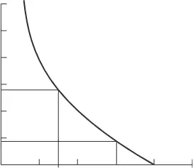
Using the time/current characteristic shown, identify the approximate disconnection time at a fault current of 50 A for the depicted overcurrent protective device.
0.08 s
0.8 s
8 s
80 s
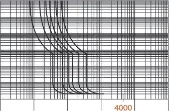
According to the time/current characteristics for a Type B MCB to BS EN 60898, what is the approximate disconnection time when the fault current is 4000 A?
2 s
0.2 s
0.02 s
0.002 s
A 6 A Type B MCB to BS EN 60898 protecting a domestic lighting circuit must operate within 0.4 s. What minimum prospective short-circuit current ensures tripping under fault conditions, based on the multiple associated with Type B?
12 A
18 A
24 A
30 A
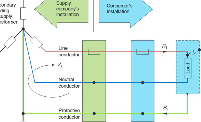
In a TN-S (cable sheath earth) system, identify what R1 and R2 represent in the earth fault loop path shown in the diagram of the supply and consumer installations with a fault at the load.
R1 is the resistance of the line conductor and R2 is the resistance of the earth conductor
R1 is the resistance of the neutral conductor and R2 is the resistance of the line conductor
R1 is the resistance of the protective devices and R2 is the resistance of the transformer secondary
R1 is the resistance of the consumer’s casing and R2 is the resistance of the meter tails
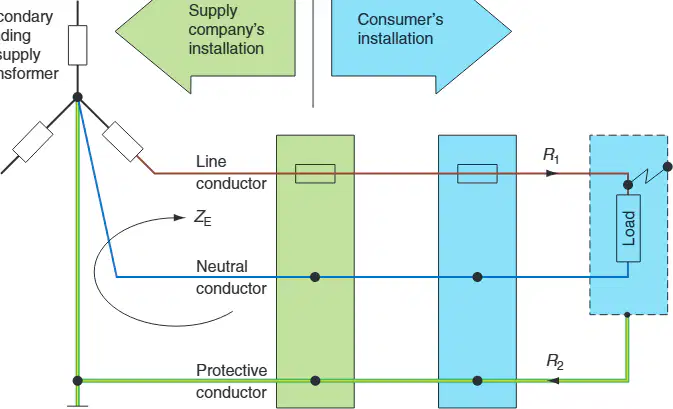
State the complete earth fault loop impedance formula for a TN-S system as described in the text accompanying the diagram of the earth fault loop path.
Zs=Ze+(R1+R2)
Zs=Ze+R1−R2
Zs=R1+R2
Zs=Ze−(R1+R2)
A 20 A radial socket outlet circuit is wired in 2.5 mm 2 PVC cable incorporating a 1.5 mm 2 CPC. The cable length is 30 m in an ambient temperature of 20°C and the measured earth fault loop impedance of the supply is Ze=0.5Ω . Using the resistance per metre value (R1+R2) of 19.51×10⁻³Ω /m for this cable combination, what is the value of (R1+R2) for 30 m before applying the fault-temperature factor?
0.585 Ω
0.702 Ω
1.202 Ω
0.195 Ω
For the same 30 m circuit, under fault conditions the cable resistance must be multiplied by the factor 1.20. What is the cable resistance under fault conditions?
0.702 Ω
0.585 Ω
0.500 Ω
1.202 Ω
With Ze=0.5Ω and the cable resistance under fault conditions of 0.702 Ω, what is the total earth fault loop impedance Zs for the circuit?
1.202 Ω
1.000 Ω
0.702 Ω
0.585 Ω

From the resistance table for copper conductors, what is the resistance per metre (R1+R2) in mΩ/m for a 2.5 mm 2 phase conductor with a 1.5 mm 2 protective conductor at 20°C?
19.51 mΩ/m
25.51 mΩ/m
14.82 mΩ/m
10.49 mΩ/m
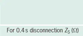
According to the maximum earth fault loop impedance table for MCB Type B devices (BS EN 60898) with a required disconnection time of 0.4 s, what is the maximum measured Zs for a 20 A device?
2.3 Ω
2.87 Ω
1.84 Ω
1.15 Ω
When the protective conductor cross-section does not comply with the tabulated sizes, which formula must be used to determine the minimum cross-sectional area S of the protective conductor?
S=kI2t
S=kIt
S=I2tk
S=I2tk
According to the stated guidelines, which rule applies to protective conductor size when the line conductor cross-section is greater than 35 mm 2 ?
The protective conductor should be half the size of the line conductor
The protective conductor should equal the line conductor
The protective conductor should be 16 mm 2
The protective conductor should be one quarter the size of the line conductor
Example 1: A 230 V ring main circuit of socket outlets is wired in 2.5 mm 2 single PVC copper cables with a separate 1.5 mm 2 CPC. An earth fault loop impedance test identifies Zs as 1.15 Ω. Verify by calculation the minimum cross-sectional area S required for the CPC when the protective device is a 30 A semi-enclosed fuse, using t=0.4 s and k=115 .
1.10 mm 2
0.75 mm 2
1.50 mm 2
0.49 mm 2
In Example 1, what maximum fault current I is used for the calculation when V=230 V and Zs=1.15Ω ?
200 A
90 A
115 A
30 A
Example 2: A TN supply feeds a domestic immersion heater wired in 2.5 mm 2 PVC insulated copper cable and incorporates a 1.5 mm 2 CPC. The circuit is protected by a 15 A semi-enclosed fuse to BS 3036. For final circuits less than 32 A the maximum operating time is 0.4 s. Using I=90 A (the prospective fault current given to operate the device in 0.4 s), t=0.4 s and k=115 , what is the minimum cross-sectional area S required by calculation for the CPC?
0.49 mm 2
1.10 mm 2
1.50 mm 2
0.75 mm 2
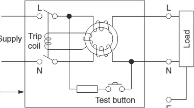
According to the section on additional protection, which statement best describes how a single-phase RCD trips under earth fault conditions?
An out-of-balance flux in the core induces an emf in the trip coil due to unequal line and neutral currents
A thermal element overheats when the line current exceeds the rating and opens the switch
A voltage drop across the neutral causes the device to latch mechanically
A magnetic field from the casing triggers a relay regardless of current balance
Modern RCDs have tripping sensitivities that allow isolation before the lower lethal limit to humans is reached. What sensitivity range is stated for modern RCDs?
10–30 mA
30–50 mA
50–100 mA
1–5 mA
What objective of the Regulations is stated for earth fault protection devices in final circuits not exceeding 32 A?
Remove earth fault current very quickly (less than 0.4 s) and limit exposed metal part voltage under fault to not more than 50 V
Ensure disconnection within 5 s and limit voltage to 120 V
Provide overload protection only for circuits above 32 A
Maintain the earth loop impedance regardless of bonding deterioration

