
 Worksheets
Diode Rectifiers Worksheet Extraction
Total questions: 14
Worksheet time: 7mins
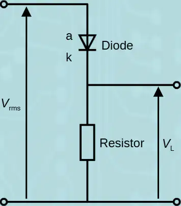
The supply voltage for a half-wave rectifier circuit is 8 V rms. Using the relationship Vdc≈0.4×Vrms , what is the average DC output? Give your answer in volts to 1 d.p.
3.2 V
3.0 V
4.0 V
2.6 V
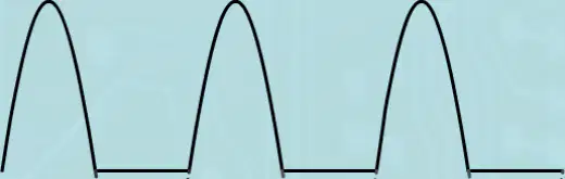
Refer to the illustrated waveforms showing half‑wave rectification with missing output during negative input half‑cycles. Why is half‑wave rectification described as inefficient in the material?
There is a gap during negative input half‑cycles when power is not supplied to the load
It requires more diodes than full‑wave rectification
It produces a higher average DC output than full‑wave rectification
It inverts the positive half‑cycles into negative ones
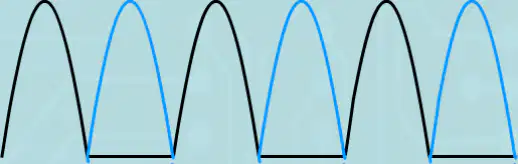
Using the illustrated comparison of half‑wave and full‑wave rectification, what happens to the negative half‑cycles in full‑wave rectification?
They are effectively inverted to become useful, positive half‑cycles
They are clipped to zero without inversion
They are amplified but remain negative
They are unchanged and pass to the load as negative
According to the content, which practical circuits implement full‑wave rectification?
Centre‑tapped rectifier
Bridge rectifier
Zener voltage regulator
Voltage doubler
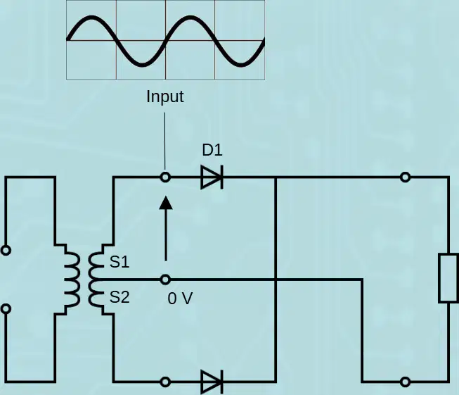
A centre‑tapped rectifier uses two diodes and a centre‑tap transformer. Based on the diagram with secondary windings S1 and S2, which statement matches this description?
It uses two diodes and a centre‑tap transformer
It uses four diodes and no transformer
It uses one diode and a centre‑tap transformer
It uses three diodes and a step‑down transformer without a centre tap
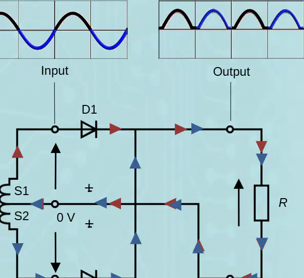
Where is the output voltage measured in the centre‑tapped rectifier circuit shown?
Across the load resistor
Across the centre‑tap node
Across diode D1 only
Across the transformer primary
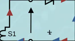
According to the annotated conduction arrows, which diode conducts during the positive half‑cycles of the input in the centre‑tapped rectifier?
D1
D2
Both D1 and D2
Neither diode conducts
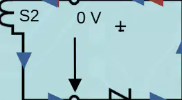
According to the annotated conduction arrows, which diode conducts during the negative half‑cycles of the input in the centre‑tapped rectifier?
D2
D1
Both D1 and D2
Neither diode conducts
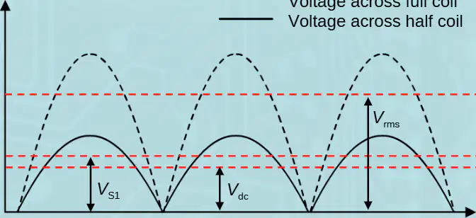
The average DC output for the centre‑tapped rectifier is given by this equation: Vdc≈0.8×VS1 . In this context, what does VS1 represent?
RMS voltage across winding S1
Peak voltage across the full secondary
RMS voltage across the entire coil
Average voltage across the load
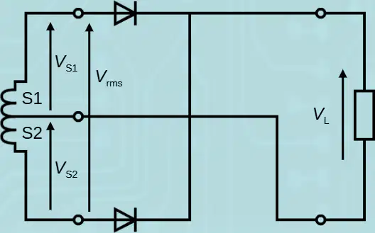
In a centre‑tapped transformer, what is the relationship between VS1 and the rms voltage across the entire power‑supply coil?
VS1 equals half the rms voltage across the entire coil
VS1 equals the full rms voltage across the entire coil
VS1 is twice the rms voltage across the entire coil
VS1 equals one‑quarter of the rms voltage across the entire coil
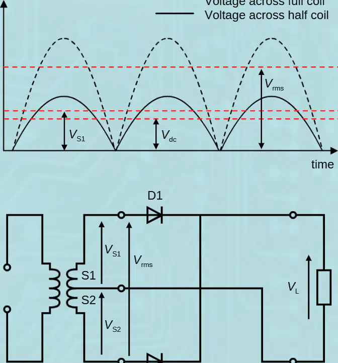
Using the stated relationships, what is the overall equation for the average DC output of a centre‑tapped rectifier in terms of the full‑coil rms voltage?
Vdc≈0.4×Vrms
Vdc≈0.8×Vrms
Vdc≈1.6×Vrms
Vdc≈0.2×Vrms
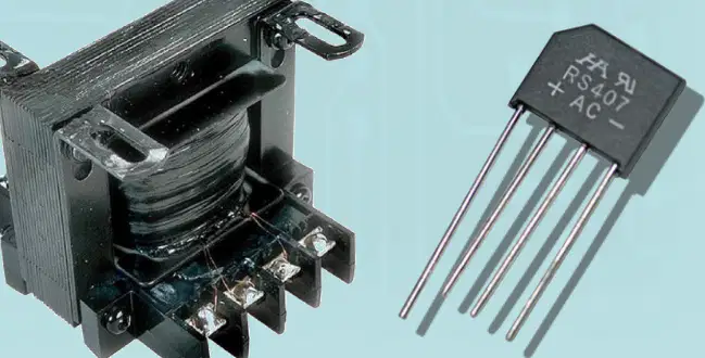
Design comparison: what advantage of the bridge rectifier is stated?
It is a cheaper and lighter design
It requires no diodes
It produces pure DC with zero ripple without any capacitor
It eliminates the need for a transformer
Ripple factor description: what does the ripple factor describe according to the text?
How wavy a voltage output is
The maximum current rating of a diode
The input frequency only
The efficiency of a transformer
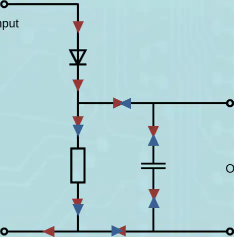
Smoothing capacitor behavior: which statements describe how the smoothing capacitor operates in the circuit shown? Select all that apply.
It charges during each positive half-cycle of the output waveform
It discharges until the next positive half-cycle arrives
It eliminates ripple completely under all conditions
It only operates during negative half-cycles

