
 Worksheets
ELECTROMAGNETISM
Total questions: 50
Worksheet time: 13hrs 30mins
Magnetic field produced around a straight conductor due to current in it is given by
Fleming's right hand rule
Right hand grip rule
Clock rule
Fleming's left hand rule

b) based on the diagram above, choose the direction of the forces that act on the sides AB and CD of the coil.
AB:UPWARD;CD:DOWNWARD
AB:DOWNWARD;CD:UPWARD

The figure shows the structure of a motor. Which of the following will not affect the speed of rotation of the motor?
The current in the coil
Strength of the magnetic field
The number of turns of wire in the coil
The direction of the current in the coil

Figure 1 and Figure 2 show the structures of a d.c motor and a d.c. motor respectively. State the change of energy that occurs in a motor.
Electrical energy to kinetic energy
Kinetic energy to electrical energy
What does the thumb indicate in flemings left hand rule?
Force
Motion
Current
Magnetic field direction
Name one factor that does not affect the size of a force in on a current-carrying conductor placed in a magnetic field?
Gravity
Magnetic flux density/size of magnetic field
Size of the current
Length of the conductor
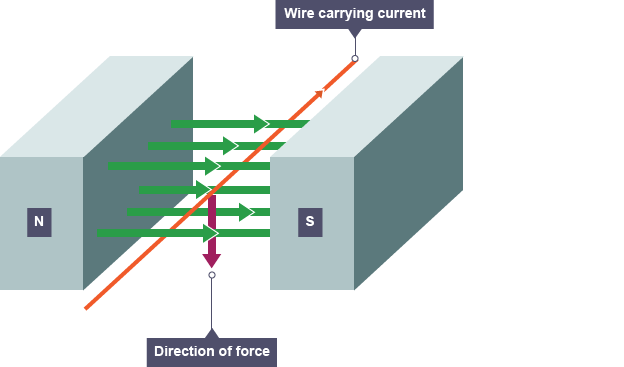
Why might a current-carrying wire be placed between a magnetic field?
To increase the current from the interaction of magnetic fields
To increase the voltage from the interaction of magnetic fields
To produce a force from the interaction of magnetic fields

c represented by
direction of magnetic field
direction of rotation
direction of force
direction of magnitude current

What is the functions of commutator?
Reverse the direction of current in the coil every half rotation so that the coil continues to turn in same direction
To contact with the commutator so the current from the battery enters the coil.
Push the brush so it will always contact with the commutator.

Diagram shows a coil placed between the poles of a permanent magnet and is connected to the external circuit.Determine the direction of rotation of the coil when the switch is closed.
Clock wise
Anti Clock wise
Alternately, anticlockwise then clockwise
Alternately, clockwise then anticlockwise

Diagram shows a coil placed between two opposite magnetic poles. An electric current flows through the coil producing a pair of turning force, F.Which diagram shows the correct catapult field ?


Diagram shows a current–carrying conductor placed between the poles of two magnet bars. Which diagram shows the resulting magnetic field ?


Diagram shows a current – carrying conductor in magnetic field. What is the direction of the force that acts on the conductor ?
A
B
C
D
The speed of direct current motor can be reduced by
increasing the amount of current
increasing the strength of magnet
increasing number of turns of coil
increasing the resistance of coil wire

Summary of the given simulation
Only motion of magnet induce emf
Only Motion of coil induce emf
Relative motion between coil and magnet induce emf
without any movement between them we can get induce emf
The magnitude of the induced emf in a circuit is equal to the magnetic flux through the circuit
True
False
changing magnetic fields can set up current loops in nearby metal bodies. they dissipate electrical energy as heat, such currents are called
Henry Currents
Faraday Currents
Eddy currents
Inductance current
AC generator works on the principle of
fleming Right hand rule
Fleming Left hand rule
Ampere rule
Right hand thumb rule

What does this symbol represent
Direct Current
Damping Current
Dancing Current
Alternating current

Current is maximum in AC generator when
Area Vector is parallel to magnetic field
Area Vector is Antiparallel to magnetic field
Area Vector is 120 degree with magnetic field
Area Vector is Perpendicular to magnetic field

The scenario shown induces a voltage of magnitude V. If the magnet has twice the magnetic field but its motion stopped, how would the induced voltage change?
Voltage would be twice as large in the same direction.
Voltage would be half as large in the same direction.
Voltage would be twice as large in the opposite direction.
No voltage would be induced in the coil.

The device pictured is a ______ and its purpose is to ________.
transformer, covert high voltage to low voltage
motor, convert electricity to kinetic energy
generator, convert kinetic energy to electricity
electromagnet, convert current into magnetic field

The device pictured is a ______ and its purpose is to ________.
transformer, covert high voltage to low voltage
motor, convert electricity to kinetic energy
generator, convert kinetic energy to electricity
electromagnet, convert current into magnetic field
A transformer consists of
Metal Core
Metal core and coiled wire
Metal core and polymer wire
Polymer core and metal wire
Select the facts about transformer.
Will not work with DC and AC
Will not work with DC
AC will produce change in magnetic field
AC will induce current
Is the core insulated?
Yes
No
The insulation at the transformer's core is meant for
to avoid sharp edges.
to avoid corrosion.
to avoid electrical contact.
to reduce power loss.
Primary loop is connected to the supply while secondary loop is connected to the load.
True
False
Step-up transformer is a transformer that increases...
voltage.
current.
resistance.
conductance.
A secondary coil of a transformer has 500 windings. It was supplied with 200 V. How many windings needed at primary coil to produce 100 V.
(a)
A secondary coil of a transformer is supplied with voltage source, while the primary coil induces voltage (emf).
True
False
Select the correct characteristics for ideal transformers.
Zero leakage flux.
The wire have no resistance.
No hysteresis or eddy currents.
Has similar windings at both primary and secondary coils.
Efficiency of a transformer is
(output current)/(input current) x100%
(output voltage)/(input voltage) x100%
(output loss)/(input loss) x100%
(output power)/(input power) x100%
A transformer has an output power of 500W. It also has core losses and copper loss of 10W. Determine the efficiency (%) of the transformer.
(a)

Laminated insulation are normally used in the transformer:
To reduce the hysteresis effect
To increase the hysteresis effect
To reduce the effect of eddy current
To increase the effect of eddy current
choose all step down transformers
TV adapter
Mobile charger
Transformer outside the homes
Transformers outside power generating stations
Increasing the number of turns of wire on the secondary of a transformer will:
decrease the secondary current
increase the primary current
increase the secondary current
have no effect on the secondary current
If dc voltage is applied to the primary of a transformer it may:
Work
Burn the winding
Give lower voltage on the secondary side
Give higher voltage on the secondary side
Is the core insulated?
Yes
No
IDEAL TRANSFORMERS WILL HAVE ------ EFFICIENCY
2%
5%
98%
100%
IN -------- TRANSFORMER LOSSES ARE ZERO.
PRACTICAL
IDEAL
ISOLATION
Which of the following is an example of appliance using alternating power source?



