
 Worksheets
logo
Total questions: 101
Worksheet time: 8hrs 25mins
What is the part of the PLC called where inputs and outputs are connected?
Memory
Input /output interface
Processor
Power supply
Where does PLC stores its program?
Input device
Power supply
Programming device
Memory
Which of the following is a PLC input device?
Fan
Motor
Sensor
Light
Which of the following is NOT part of a basic PLC system?
Relay box
Power supply
Memory
CPU
Which of the following is an output device?
Keypad
Distance sensor
Sound sensor
Motor
A PLC is a computer used for industrial automation.
True
False
None of the above
Which of the following is the application of PLC?
Wending machines
Automatic door
Cereal filling systems
All of the above
Which of the following is an example of discrete (digital) control?
Turning a lamp ON or OFF
Varying the brightness of a lamp
Varying the volume of a music system
Controlling the speed of a fan
What are solenoids, lamps, and motors connected to?
Analog input
Analog output
Digital input
Digital output
Gear Box is used to decrease the speed and increase the torque.
True
False
None of the above
What does PLC stands for?
Programmable logic controller
Programming logic computer
Programming ladder CPU
Programmable limited control
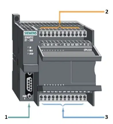
Select the sequence of label from the below option.
1.programming port 2.output port 3.Input port
1.programming port 2.Input port 3.output port
1.output port. 2.programming port 3.Input port
What is the job of the CPU?
Forms the interface between input field devices to the controller.
Store and run the PLC software program.
To provide DC power to the PLC.
Forms the interface between output field devices to the controller
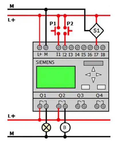
Specify the inputs used in the wiring diagram of the PLC module given below
N.O. pushbutton 1, N.O pushbutton 2 & 3 wired ultrasonic sensor
N.O. pushbutton 1, N.O pushbutton 2
Lamp and Buzzer
3 wired ultrasonic sensor
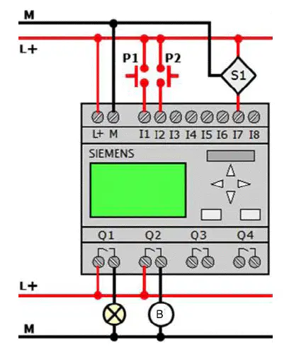
Specify the outputs used in the wiring diagram of the PLC module given below
A. N.O. pushbutton 1, N.O pushbutton 2 & 3 wired ultrasonic sensor
N.O. pushbutton 1, N.O pushbutton 2
Lamp and Buzzer
3 wired ultrasonic sensor
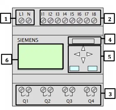
What is name of the PLC part labeled '2'
Output
Power Supply
Inputs
Module Slot
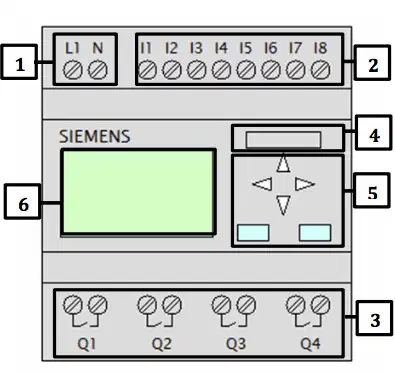
What is name of the PLC part labeled '3'
Output
Power Supply
Inputs
Module Slot
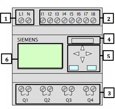
What is name of the PLC part labeled '1'
Output
Power Supply
Inputs
Module Slot
Few applications of PLC are
Automatic door
cereal filling systems
wending Machines
all of the above
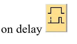
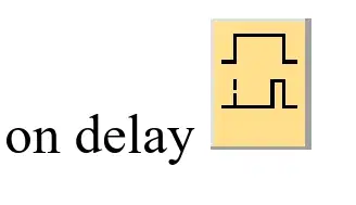
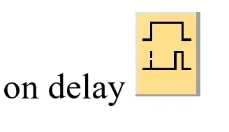
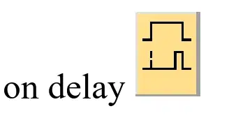
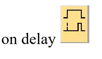
Which function block of the LOGO! corresponds to the special function "ON DELAY":


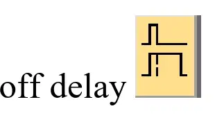
Which function block of the LOGO! corresponds to the special function "OFF DELAY":
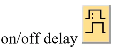
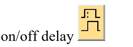
Which function block of the LOGO! corresponds to the special function "ON/OFF DELAY":
Which function block of the LOGO! corresponds to the special function "RETENTATIVE ON DELAY":
. Which function block of the LOGO! corresponds to the special function "HOURS COUNTER":


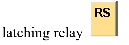
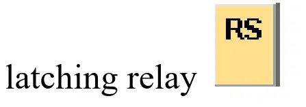
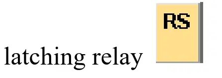
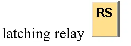
. . Which function block of the LOGO! corresponds to the special function "LATCHING RELAY":


Disadvantage of PLC is _
A. Security
B. Fixed program application
C. Documentation
D. Pilot running
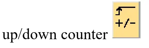
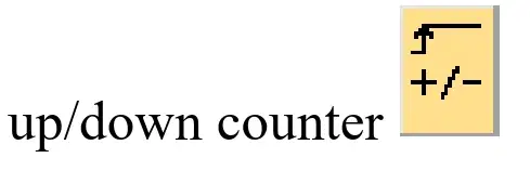
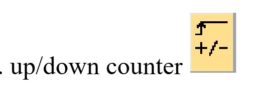
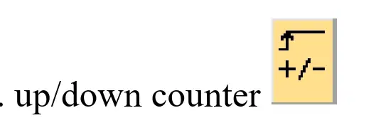
Which function block of the LOGO! corresponds to the special function "UP/DOWN COUNTER":
. .Which function block of the LOGO! corresponds to the special function "ASYNCHRONOUS PULSE GENERATOR":
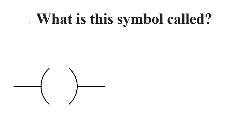
A. Normally Close contact
B. Output Coil
C. Normally Open contact
D. Timer
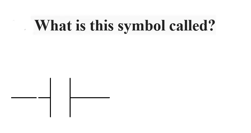
A. Normally Close contact
B. Output coil
C. Normally Open contact
D. Timer
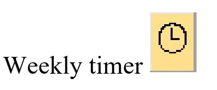
Which function block of the LOGO! corresponds to the special function "WEEKLY TIMER":


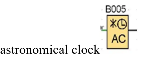
Which function block of the LOGO! corresponds to the special function "ASTRONOMICAL CLOCK":
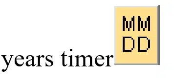
Which function block of the LOGO! corresponds to the special function "YEARLY TIMER":
Supply voltage for LOGO230! may be
A)230V…115V
b)230V...120V
c)240V...115V
D)240V...115V
How can you program LOGO!
Directly from the module keyboard;
From a computer equipped with LOGO! Soft Comfort;
installing a programmed memory module;
A, B, C are correct;
using a remote workstation.
Maximum load per output of LOGO! at voltage = 24V
0.1A;
30mA;
0.3A;
50mA;
10A.
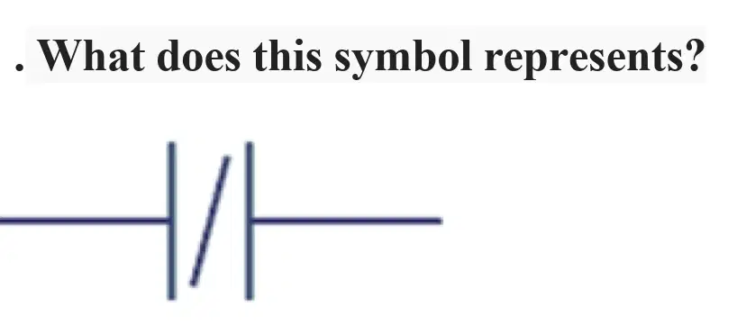
A. A normal output
B. Normally open push button
C. Normally closed push button
D. Inverted output
Where SCADA can be used?
A. Manufacturing
B. Mass transit
C. Traffic signals
D. All of the above
The standard form of HMI is
A. Human Master Interface
B. Human Machine Interface
C. Human Main Interface
D. None of the above
Scada is an abbreviation for:
Supervisory Control and Document Acquisition
Supervisory Control and Data Acquisition
Supervisory Column and Data Assessment
Supervisory Column and Data Assessment
The SCADA systems used to __
A. Monitor
B. Control
C. Both a and b
D. None of the above
Which of the following is the heart of a SCADA system?
PLC
HMI
Alarm task
I/O
DCS is a __
Distributed Control System
Data Control System
Data Column System
Distributed Column System
In case of an emergency, the display will show "ATTENTION"
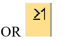
Turn ON a lamp using either I1 or I2 or both
Cable conductor cross-sections for LOGO logic controllers
From 1.5 mm2 to 2.5 mm2
From 2.5 mm2 to 3.5 mm2
From 3.5 mm2 to 4.5 mm2
From 4.5 mm2 to 5.5 mm2
Turn ON and Turn OFF a motor using the same function block
The engine turns on and off at the specified time intervals: 10 sec. works, 5 sec. pause.
What logic modules are included in the LOGO! family?
A)LOGO!Basic, LOGO!Pure, LOGO!Long, LOGO!Bus;
b)LOGO!Basic, LOGO!Pure, LOGO!Power, LOGO!Bus;
c)LOGO!Basic, LOGO!Pure, LOGO!Power, LOGO!Contact;
D)LOGO!Power, LOGO!Pure, , LOGO!Bus;
e)LOGO!Contact, LOGO!Pure, LOGO!Long, LOGO!Bus..
What does the letter C mean in the markings of LOGO! modules?
A)Module equipped with built-in AS-i - interface;
b)Long version module (12 digital inputs/8 digital outputs);
c)Module with built-in real time clock;
D)Module with outputs in the form of normally open relay contacts;
e)Module supply voltage.
What does the letter L mean in the markings of LOGO! modules?
A)Module equipped with built-in AS-i - interface;
b)Long version module (12 digital inputs/8 digital outputs);
c)Module with built-in real time clock;
D)Module with outputs in the form of normally open relay contacts;
e)Module supply voltage
Gate should open automatically at sunrise and close again after sunset
What does the number 11 mean in the markings of LOGO! modules?
A)Module equipped with built-in AS-i interface;
b)Long version module (12 digital inputs/8 digital outputs);
c)Module with built-in real time clock;
D)Module with outputs in the form of normally open relay contacts;
e)Module supply voltage.
How many digital inputs and digital outputs are there in LOGO!Basic?
A)12 digital inputs 8 digital outputs;
b)4 digital inputs 6 digital outputs;
c)16 digital inputs 8 digital outputs;
D)8 digital inputs 4 digital outputs;
e)8 digital inputs 12 digital outputs.
Which element is represented by the letter I in the LOGO!Soft_Comfort program?
Exit;
Discrete input;
Analog input;
analog output;
AS-i inputs.
Which of the following languages is a high-level graphical language?
in C++;
assembler;
Pascal;
SFC;
Delphi.
Which element is denoted by the letters AI in the LOGO!Soft_Comfort program?
Exit;
Discrete input;
Analog input;
analog output;
AS-i inputs.
Which element is denoted by the letters AQ in the LOGO!Soft_Comfort program?
Exit;
Discrete input;
Analog input;
analog output;
AS-i inputs.
Which of the following features are typical for the further operation of the LOGO! in the event of a power failure (shutdown):
internal clock in LOGO! continue to work from backup power supply;
switching states and counter values are always stored in special functions;
the REM memory area is completely erased;
saving the current values of block variables in the RAM memory area;
all answers are correct.
Which element is denoted by the letter Q in the LOGO!Soft_Comfort program?
discrete output;
Discrete input;
Analog input;
analog output;
AS-i inputs.
What is meant by markers when programming a LOGO! in FBD language:
A)virtual outputs that have the same value at their output as at their input;
b)open connector;
c)controller program execution status flags;
D)blocks that allow you to display various data on the display controllers;
e)there are no such program elements on FBD
The LOGO! controller memory required for special functions is divided into 4 areas. What is stored in the PAR memory area:
A)current actual values;
b)stores initial (set) values;
c)used by the controller to implement time functions;
D)the actual values to be saved;
e)information about the progress of the program execution by the controller.
The maximum number of elements used when compiling a program in the FBD language, connected in series from input to output, for LOGO! must not exceed:
A)56;
b)48;
c)7;
D)10;
e)8.
The typical value of the current of one discrete input at an input voltage of 24V is about ...
A)5mA
b)2mA
c)10mA
D)8mA
e)0mA.
Switch OFF a machine after a certain time
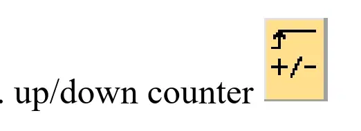
Count the number of produced Cola cans

Memory modules...
Designed for long-term storage of programs and data;
Transferring programs from one logical module to another
To save data during power outages of logic modules;
Correct answers A and B;
All answers are correct.
What does the DM8 marking mean?
A)Module for input-output of discrete signals;
b)Analog module;
c)Communication module;
D)Module with NO outputs;
e)Built-in weekly timer.
Which of the following elements are accepted by the LOGO! how are the sensors?
push buttons
switches
photoelectric barriers
control switches
all answers are correct
What are the special analog inputs for
thermistors and voltmeter;
connection of resistance thermometers and thermocouples;
transistor and diode
ammeter and diode
ammeter and voltmeter
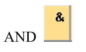
Turn ON a machine when the I1 is pressed and the machine door is closed
Choose the most complete and correct definition of a PLC
PLC is an information channel that combines all the functional blocks of the MPS and provides data exchange in the form of binary numbers
PLC - a device that directly carries out the data processing process and program control of this process
PLC is a combinational logic circuit with the help of which the information processing process is carried out
PLC is a device designed to collect, convert, process, store information and generate signals for indication and control
A PLC is an analog device with built-in microcircuits containing specific information
How LOGO logic modules are connected to the network.
Through communication modules
Satellite communications
Super high speed bus
telephone lines
Modem
What does the LOGO! 24Ro
A)Module power supply =24V, output in the form of closing relay contacts, without keyboard and display;
b)Module power supply =12V, output in the form of closing relay contacts, with keypad and display;
c)Module power supply =24V, with keypad and display;
D)Module power supply =12V, output in the form of closing relay contacts, without keyboard and display;
e)Power supply of the module =24V, output in the form of closing relay contacts.
State the main advantages of the PLC polling system.
A)ease of implementation, ease of programming;
b)high system sensitivity;
c)high speed of the system;
D)no merit;
e)small error.
Select a communication module from the following
LOGO CM
LOGO RS
LOGO VS
LOGO FBD
LOGO LD
The typical voltage value of one digital input at an input current of 10mA is about…
A)20V;
b)10V;
c)24V;
D)5V;
e)1B.
Scope of PC-based PLC:
A)With several inputs and outputs of the object, it is necessary to perform a large amount of calculations in a sufficiently small time interval;
b)Automation tools operate in an environment not too different from that of conventional PCs;
c)It is advisable to program the functions implemented by the controller not in one of the standard technological languages, but in an ordinary high-level language;
D)Powerful support for the operator's work implemented in conventional controllers (diagnostics, troubleshooting without stopping the controller, software modification during the operation of the automation system);
e)All answers are correct.
The main differences between a small-scale DCS and network controllers:
A)In a slightly larger variety of controller modifications;
b)In greater power of central processors;
c)In a more developed and flexible network structure;
D)In that they are designed to work in various environmental conditions;
e)All answers.
All discrete inputs (general version) of the controllers are designed to receive standard signals with a level of _??_V DC.
A)24V;
b)12V;
c)48;
D)6B;
e)Don't know.
How many digital and analog inputs can the maximum configuration of LOGO!
24 discrete and 8 analog inputs
8 discrete and 24 analog
16 discrete and 8 analog
24 discrete and 16 analog
8 discrete and 16 analog
DM8 expansion modules can only be connected to modules with the same level:
A)Supply voltage and type of current;
b)Voltage and marking;
c)resistance and current;
D)Power, body color and resistance;
e)power and direct current.
Programming logic modules LOGO! Can be performed:
A)Directly from the keyboard of the LOGO! basic;
b)In the ISaGraf environment;
c)In Scada system;
D)In the C++ environment;
e)In the Pascal programming environment.
What languages are LOGO! controllers programmed in:
A)C++, Visual Basic;
b)assembler;
c)FBD, LAD;
D)SFC,LD;
e)FD, LD.
What does the SF library contain?
A)A set of special-purpose functions;
b)Trigonometric functions;
c)Timers and counters;
D)A set of functions containing the basic logical operations;
e)Logarithmic functions.
What are the interconnected segments of industrial networks.
Optical fiber cables
routers
infrared ports
telephone lines
Satellite connection
The combination of all LOGO! modules into a single device is carried out through:
A)Introduction of a new module;
b)external bus;
c)Single common module;
D)Inner bus;
e)Embedded microprocessor
In what form does the signal transmitted from the sensors / PLC enter the monitoring (supervision) control system of the DCS
In digital sequence
In analog sequence
As an encrypted message
Plain text
It can't be transferred!
According to the technical capabilities that determine the level of tasks to be solved, PLCs are divided into classes:
A)Nano;
b)Micro;
c)Small;
D)Medium and large;
e)All answers.
Logical expressions in this language are described in the form of relays and contacts
SFC (Sequential Function Chart)
LD (Ladder Diagram)
FBD (Functional Block Diagram)
ST (Structured Text)
IL (Instruction List)
A graphical language used to describe an algorithm as a set of connected pairs: a step and a transition
SFC (Sequential Function Chart)
LD (Ladder Diagram)
FBD (Functional Block Diagram)
ST (Structured Text)
IL (Instruction List)
What does real-time data transmission mean?
There should be no data transfer delay and no information loss;
There should be no delay in data transfer, but some loss of information is possible
There should be no loss of information, but there may be a delay
There should be no loss of information
There should be no time delay in the transmission of information
Which parameters belong to the special function "off delay"
Trg, R, Q
Trg, T, R, Q
T, R, Q
Trg, T, R
T, Q
Select an analog input module in the LOGO! family
DM8
AM2
LON
CM8
RS2
How many outputs can be served by the maximum configuration of the logic module LOGO24!
16
4
24
14
8
Communication module LOGO! CM supports:
4 discrete inputs and 4 discrete outputs
4 analog inputs and 4 analog outputs
4 virtual discrete inputs and 4 virtual discrete outputs
It has neither analog nor discrete inputs and outputs
2 analog inputs
The LOGO!AM2 module is designed for:
generation of voltage signals 0…10V or current strength 0…20mA
increasing the number of discrete inputs
temperature measurements with Pt100 sensors
increasing the number of analog inputs
increasing the number of special-purpose functions
The total number of connected analog modules is limited to
Required value of analog inputs
Required value of analog outputs
The maximum configuration of the logic module
The total number of pluggable analog modules is not limited at all
Required value of digital inputs and outputs
What does the GF library contain?
A set of special-purpose functions
Trigonometric functions
Timers and counters
A set of functions containing the basic logical operations
Logarithmic functions
Which two libraries group all the functions built into the operating system of LOGO! logic modules
GF and SF
NF and MF
NF and FF
GF and NF
SF and NF
To avoid installation errors, all DM8 modules are equipped with
Coding grooves and pins
Special terminals
Inputs and outputs of various colors
Translation slider
indicator

