
 Worksheets
RC - ELEX 2
Total questions: 50
Worksheet time: 25mins
1. The B-H curve for _____ will be a straight line passing through the origin.
silicon steel
soft iron
hardened steel
air
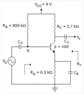
2. The amplifier circuit shown below uses a silicon transistor. The capacitors C_C and C_E can be assumed to be short at signal frequency and the effect of output resistance r_0 can be ignored. If C_E is disconnected from the circuit, which one of the following statements is TRUE?
Both input resistance Ri and the magnitude of voltage gain Av increase
The input resistance Ri decreases and the magnitude of voltage gain Av decreases
The input resistance Ri increases and the magnitude of voltage gain Av decreases
Both input resistance Ri and the magnitude of voltage gain Av decrease
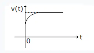
3. When a current source I is suddenly connected across a two terminal relaxed RC circuit at time t = 0, the voltage across the current source is shown in figure. The RC circuit is ______.
a parallel combination of R and C
a series combination of R and C
a pure capacitor
a series combination of R and parallel combination of R and C
4. All but which one of the following statements regarding extrinsic semiconducting silicon is true?
Electrons are donated to the conduction band in n-type silicon.
The Fermi energy is raised by Group V elements in extrinsic silicon
Group III elements accept electrons from the valence band of silicon.
The number of n-type carriers equals the number of p-type carriers in extrinsic silicon.
5. In an ac circuit, what can be the maximum and minimum values of power factor?
1 and 0
2 and 0
0 and -1
1 and -1
6. For all resistor wattage ratings except 1/8 watt, what is the maximum allowable change in resistance for a 1000-hour rated load life test?
10%
5%
15%
12%
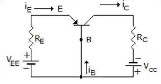
7. Si transistor of the following figure has a α = 0.9 and I_CE = 0, V_EE = 5 V and Vcc = 13 V, then R_E will be ____ if I_EQ = 1 mA.
4.3 kΩ
5 kΩ
3 kΩ
4 kΩ
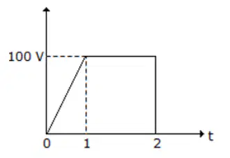
8. What is the rms value of the wave shown in the figure?
about 25 V
about 95 V
about 50 V
about 80 V
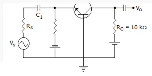
9. The 'h' parameters of the circuit shown in the figure are h_ib = 25 Ω, h_fb = 0.999 and h_ob = 10¯⁶ Ω. What is the voltage gain?
400
100
300
200
10. If the cross-sectional area of a magnetic field increases, but the flux remains the same, the flux density _______.
increases
remains the same
doubles
decreases
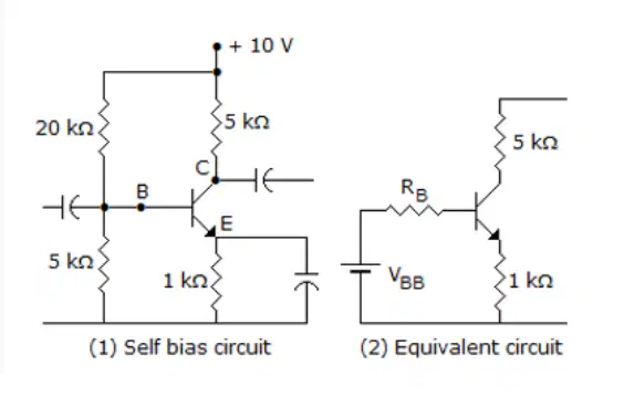
11. The figure shows the self-bias circuit for CE amplifier and its equivalent circuit. What are V_BB and R_B respectively?
2 V and 10 kΩ
5 V and 4 kΩ
2 V and 4 kΩ
10 V and 4 kΩ
12. An RLC series circuit is underdamped. To make it overdamped, the value of R ______.
has to be reduced to zero
has to be decreased
has to be increased to infinity
has to be increased
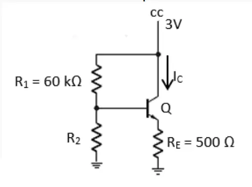
13. In the circuit shown below, the silicon npn transistor Q has a very high value of β. What is the required value of R2 in kΩ to produce Ic = 1 mA?
40
50
30
20
14. In an R-C series circuit excited by a voltage E, the charge across capacitor at t = 0^+ is ______
CE
CE [1 – e^(t/RC)]
0
infinity
15. To prevent a DC return between source and load, it is necessary to use _______.
capacitor between source and load
inductor between source and load
either resistor between source and load or inductor between source and load
resistor between source and load
16. A capacitor terminology that refers to minute and rapid fluctuations of capacitance?
Burnout
Capacitance proofing
Coronation
Scintillation
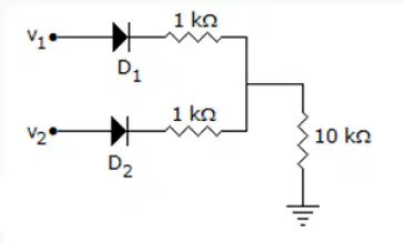
17. In figure shown, v1 = 8 V and v2 = 4 V. Which diode will conduct?
D₂ only
D₁ only
Neither D₁ nor D₂
Both D₁ and D₂
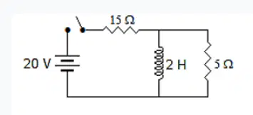
18. In figure shown, what is the current supplied by battery immediately after switching on the circuit?
4 A
10 A
0
1 A
19. The drift velocity of electrons is ______.
equal to speed of light
very small as compared to speed of light
half the speed of light
almost equal to speed of light
20. If the steel disk in a crankshaft position sensor has stopped with the tab in the magnet's air gap, the induced voltage ______.
increases
will remain constant
decreases
is zero
21. In a CE amplifier the input impedance is equal to the ratio of _______.
ac emitter voltage to ac collector current
ac base voltage to ac emitter current
ac collector voltage to ac collector current
ac base voltage to ac base current
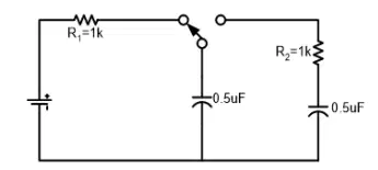
22. For the circuit shown below, different time constants are given:
1. 0.5 x 10¯³ s
2. 2 x 10¯³ s
3. 0.25 x 10¯³ s
4. 10¯³ s
What are the charging and discharging times respectively?
1, 3
2, 3
2, 4
1, 2
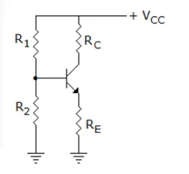
23. In figure shown, what is the saturation collector current?
Vcc/R_E
Vcc/Rc – R_E
Vcc/Rc + R_E
Vcc/Rc
24. What if you have a 12-strand conductor and each strand has a radius (one-half the diameter) of 2/10 inch, what is the square mil area of the conductor?
61,115 sq. mil
45,239 sq. mil
244,344,097 sq. mil
1,507,965 sq. mil
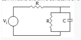
25. What is the time constant of the circuit in figure shown?
RC/2
2/RC
RC
1/2RC
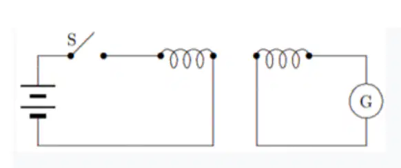
2. In the experiment shown:
there is a current in G just after S is opened or closed
the current in the battery goes through G
there is a steady reading in G as long as S is closed
a motional emf is generated when S is closed
2. Which of the following statements is false?
Distribution of a.c. is more convenient than with d.c. since voltages may be readily altered using transformers
It is cheaper to use a.c. than d.c.
An alternator is an a.c. generator
A rectifier changes d.c. to a.c
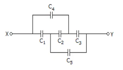
3. The capacitors C₁, C₃, C₄ and C₅ have a capacitance of 4 μF each and the capacitor C₂ has a capacitance of 10 μF. What will be the effective capacitance (in μF) between the points X and Y?
4 uF
8 uF
3 uF
6 uF
4. The surface charge density on a conductor is 1.55 x 10¯⁹ C/m². The conductor is immersed in water with ε = 78ε_0. What will be the electric field?
2 V/m
3 V/m
2.25 V/m
1.55 V/m
5. As an externally generated magnetic field through a certain conducting loop increases in magnitude, the field produced at points inside the loop by the current induced in the loop must be:
in the same direction as the applied field
decreasing the magnitude
directed opposite to the applied field
increasing the magnitude
6. The JFET in the circuit shown in figure has an I_DSS = 10 mA and Vp = -5 V. What is the value of the resistance Rs for a drain current I_DS = 6.4 mA?
156 Ω
1 kΩ
560 Ω
100 Ω
7. The output characteristics of a FET closely resemble the output characteristic of a _________valve.
triode
tetrode
diode
pentod
8. What is the best location for setting a Q-point on dc load line of an FET amplifier?
At threshold point
At mid-point
At saturation point
At cutoff point
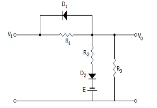
9. In the circuit shown in the given figure, the diode states at the extremely large negative values of the input voltage vi are:
D₁ off, D₂ off
D₁ off, D₂ on
D₁ on, D₂ on
D₁ on, D₂ off
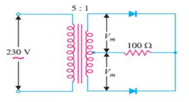
10. The figure below shows a center-tap circuit having the load resistance and transformer turn ratio given. The primary is connected to 230 V, 50 Hz supply. Find the d.c. output voltage
21.7 V
27.1 V
19.8 V
20.7 V
11. The small variation in the output voltage of a dc power supply is called _____.
surge voltage
residual voltage
ripple voltage
average voltage
12. During the positive half-cycle of the input voltage in a bridge rectifier,
two diodes are forward-biased
all diodes are forward biased
one diode is forward-biased
all diodes are reverse-biased
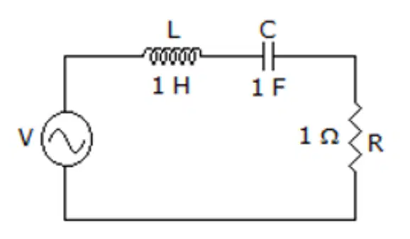
13. What is the damping coefficient for the given circuit below?
1/2
1
2
1/4
14. What is the resonant frequency of the circuit shown in the figure?
1/2pi Hz
1/22pi Hz
1/4pi Hz
1/8pi Hz
15. When a diode in a center–tapped rectifier opens, the output is
half-wave rectifier
reduced in amplitude
unaffected
0 V
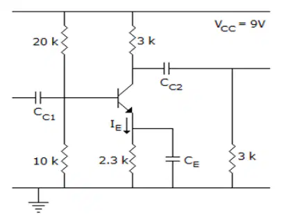
16. In the following transistor circuit V_BE = 0. 7 V, r_c = 25mV/I_E, and β and the capacitance are very large. What is ap proximately the mid-band voltage gain of the amplifier?
- 180
- 120
- 90
- 60
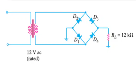
17. The bridge rectifier shown below uses silicon diodes. Find the d.c. output voltage and d.c. output current. Use simplified model for the diodes
9.19 V; 828.5 μA
9.19 V; 825.8 μA
9.91 V; 828.5 μA
9.91 V; 825.8 μA
18. Reverse saturation current in a silicon PN junction diode nearly doubles for every ____ degree rise in temperature.
50ᵒ
20ᵒ
60ᵒ
100ᵒ
19. What capacitor has a low temperature coefficient of capacitance and good stability with temperature and frequency making this a good choice for critical precision circuitry such as filter applications?
Ceramic
Electrolytic
Paper
Mica
20. As an externally generated magnetic field through a certain conducting loop increases in magnitude, the field produced at points inside the loop by the current induced in the loop must be:
directed opposite to the applied field
decreasing the magnitude
in the same direction as the applied field
increasing the magnitude
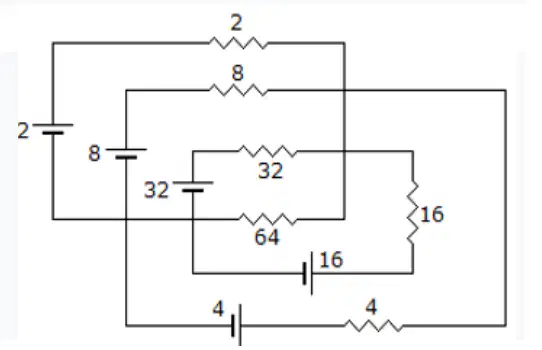
21. Find the voltage across 64 Ω resistor for the circuit shown below.
-63/64 V
-64/63 V
64/63 V
63/64 V
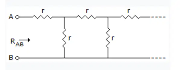
22. In the infinite ladder circuit as shown above each resistance of r Ω then find R_AB.
4r/3
3r/4
∞
1.61r
23. What resistor type is unsuited for use above 50 kHz?
Intrinsic resistor
Wirewound resistor
Film resistor
Carbon composition resistor
24. The process of changing a half-wave rectified voltage to a constant voltage is called ____.
damping
ripple suppression
ac to dc conversion
filtering
25. If both the plate area and the plate separation of a parallel-plate capacitor are doubled, the capacitance is:
halved
tripled
unchanged
doubled

