
 Worksheets
2024 - Final Examination - Engineering Drawing and CAD II
Total questions: 50
Worksheet time: 28mins
A regular cone is been cut by a plane that is perpendicular to the axis of the cone the section will be like __________. (一个规则的圆锥体被一个垂直于圆锥体轴线的平面切割,截面将像__________。)
Ellipse
Hyperbola
Circle
Triangle
When the projectors are parallel to each other and also perpendicular to the plane, the projection is called ________. (当投影仪彼此平行且也垂直于平面时,投影称为________。)
Oblique projection
Orthographic projection
Isometric projection
Perspective projection
The front view of an object is shown on which plane? (对象的前视图显示在哪个平面上?)
Profile plane
Vertical plane
Horizontal plane
Parallel plane
The side view of an object is shown on which plane? (对象的侧视图显示在哪个平面上?)
Profile plane
Vertical plane
Horizontal plane
Parallel plane
The top view of an object is shown on which plane? (对象的俯视图显示在哪个平面上?)
Profile plane
Vertical plane
Horizontal plane
Parallel plane
The type of line used to represent the cutting plane in drawing is. (在图形中用于表示切割平面的线的类型为。)


Multi-view projections are the collection of orthogonal two-dimensional projections of a three-dimensional body. (多视图投影是三维实体的正交二维投影的集合。)
True ☑
False ☒
Which of the following scales is a reducing scale?
3 : 2
1 : 3
1 : 1
1 : 0.4
Which of the following scales is neither an enlarging nor a reducing scale?
3 : 2
1 : 4
1 : 0.5
1 : 1
For the drawing sheets A2, A3, and A4 what is the width of the border?
对于图纸 A2、A3 和 A4,边框的宽度是多少?
10 mm
5 mm
15 mm
20 mm
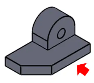
Choose the Front View of this object.


Choose the Top View of this object.
Choose the Back View of this object.
Choose the Bottom View of this object.
Choose the Left View of this object.


Choose the Right View of this object.
The sizes from A0 to A4 increase.
True
False
What is the purpose of using orthographic projection in engineering?
To represent a 3D object in 2D views for accurate measurements and visualization.
To create 3D models directly without the need for 2D views
To add artistic flair to technical drawings
To simplify complex engineering calculations
To understand some of the hidden geometry of components an imaginary plane is used to cut the object which is called _____________.
auxiliary plane
picture plane
section plane
additional plane
Which of the following is not the purpose of using a cutting (section) plane?
Interpretation of object
Visualizing of object
Cutting the objects
Invisible features
To find the true shape of the section, it must be projected on a plane parallel to the _____________.
Profile plane
Vertical plane
Auxiliary plane
Section plane
The projection of a section plane, on the plane to which it is perpendicular is a straight line.
True
False
What are the components of a bill of materials?
Item name, category, supplier, cost
Serial number, model, price, manufacturer
SKU, weight, color, dimensions
Part number, description, quantity, unit of measure, additional attributes
Why is it important to have a bill of materials in engineering drawings?
To confuse the engineers
To make the drawings look more colorful
Having a bill of materials in engineering drawings is important for ensuring accurate material selection, cost estimation, inventory management, and component identification.
To increase the weight of the final product
What information should be included in a bill of materials for effective communication?
Customer reviews, product dimensions, warranty information
Components, quantities, part numbers, descriptions, unit of measure
Manufacturing date, expiration date, price
Color, weight, material
What is dimensioning in engineering drawing?
Dimensioning in engineering drawing is the process of defining and specifying the size, shape, and other geometric characteristics of objects within the drawing using standardized symbols, lines, and notes.
Dimensioning involves adding irrelevant text to engineering drawings
Dimensioning is the process of coloring engineering drawings
Dimensioning refers to the act of signing engineering drawings
What are the different types of dimensioning techniques used in engineering drawing?
Unidirectional dimensioning, Aligned dimensioning, Angular dimensioning, Chain dimensioning, Baseline dimensioning
Inconsistent dimensioning
Irregular dimensioning
Random dimensioning
What is the purpose of dimension lines in engineering drawings?
Dimension lines are used for decoration purposes only.
Dimension lines are used to indicate the color scheme of the drawing.
Dimension lines are used to show the direction of the wind in the drawing.
Dimension lines are used to indicate the size and location of features on engineering drawings.
What are the common symbols used in dimensioning?
Squares
Triangles
Stars
Arrows, circles, lines
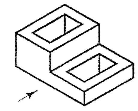
Choose the front view of the given object.


Choose the top view of the given object.
Choose the bottom view of the given object.
Choose the back view of the given object.
Choose the right view of the given object.


Choose the left view of the given object.
What is orthographic projection?
Orthographic projection is a method of representing a two-dimensional object in three dimensions.
Orthographic projection is a method of representing a three-dimensional object in two dimensions.
Orthographic projection is a method of representing a three-dimensional object in four dimensions.
Orthographic projection is a method of representing a two-dimensional object in one dimension.
Explain the difference between first angle and third angle projection.
First angle projection involves placing the object in the first quadrant, while third angle projection involves placing the object in the third quadrant.
First angle projection is used for 2D drawings only.
First angle projection involves placing the object in the second quadrant.
Third angle projection involves placing the object in the fourth quadrant.
Explain the purpose of using a title block in engineering drawings.
To write the title of the drawing in a fancy font
To provide information such as the title, scale, date, and author of the drawing
To add a decorative element to the drawing
To confuse the viewers about the content of the drawing
Technical Drawing is
A graphical representation of objects and structures
Machine
Manufacturing process
CAD software
Which one is NOT in design Process?
Communication
Visualization
Documentation
Instrumentation
What is Drawing Standards?
mentally control visual information
set of rules that govern how technical drawings are represented
methods used for technical drawings
technical graphics are used in engineering design


The name of middle view in these third angle projection
Top View
Front View
Side View

Why to Engineers make so many sketches
They like to impress regular people with their drawing ability
sketching tells a story about a design such as where it might be used
sketching allows engineers to communicate details of their design quickly
engineers use color in their design to show details like texture
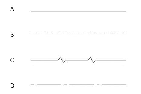
6. Which of the following represents a centre-line?
A
B
C
D
Which of these is the correct BS symbol for First Angle Projection?
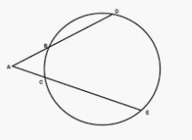
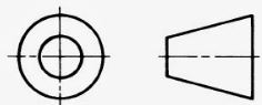
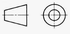
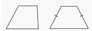
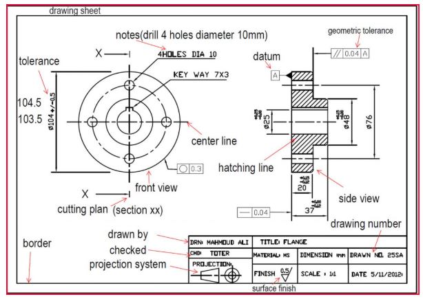
What kind of view is shown on the right hand side?
Isometric
Section
Assembly
Oblique

