
 Worksheets
AUTO2002 Engine Structure
Total questions: 20
Worksheet time: 10mins
The correct formula used to calculate the engine displacement is :
π x R2 x L x N
π2 x R x L x N
π x D x L x N
π x R2 x L2 x N
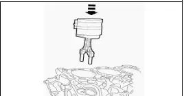
The figure shows how to :
Fix the piston to the crankshaft
Insert the piston inside the cylinder
Remove the piston from the cylinder
Fit piston rings to the piston
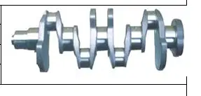
The figure shows a :
The figure shows a :
Crankshaft for a 4-cylinder engine
Camshaft for a 6-cylinder engine
Crankshaft for a 6-cylinder engine
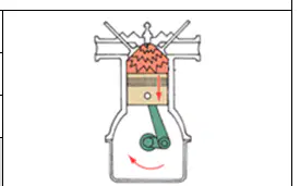
Name the stroke shown in the figure .
Compression
Intake
Exhaust
Power
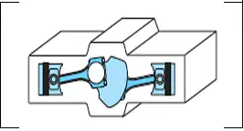
The cylinder arrangement shown in the figure is a/an :
V-type
In-line type
Opposed type
W-type
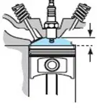
The volume above the piston with the piston at TDC is called :
Swept volume
Clearance volume
Total volume
Engine volume
A cause of blue smoke coming from the vehicle exhaust pipe is :
حالة وجود عادم (دخان) ازرق في انبوب العادم السيار يكون السبب من
Engine oil being burned
Incomplete fuel combustion
Water being vaporized in combustion chamber
Rich fuel/air mixture being ignited
The two stroke cycle engine produces a power stroke every :
4 crankshaft revolutions
3 crankshaft revolutions
2 crankshaft revolutions
1 crankshaft revolution
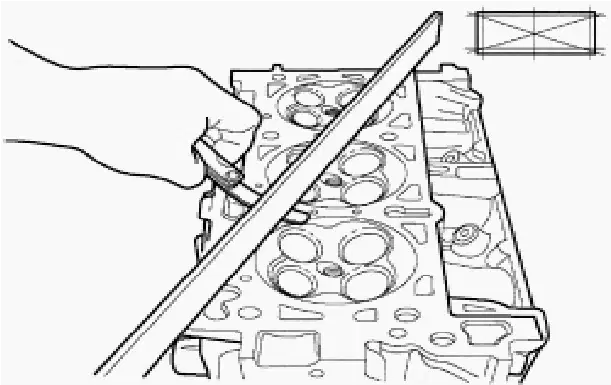
The process shown in the figure is how to check :
Cylinder head for flatness
Cylinder head for cracks
Cylinder block for flatness
Cylinder block for cracks
The correct stroke sequence of a four stroke cycle engine is :
Power–Intake–Compression–Exhaust
Intake–Compression–Exhaust–Power
Power–Compression–Intake–Exhaust
Intake–Compression–Power–Exhaust
The measure of how much the air and fuel are compressed during the compression stroke is called :
Compression ratio
Compression stroke
Combustion chamber
Combustion ratio
The torque is measured by the following formula :
Force x Distance
Force x Time
Force x Velocity
Force x Time x Distance
The distance when the piston travels from TDC to BDC is called piston :
Bore
Stroke
Total volume
Clearance volume
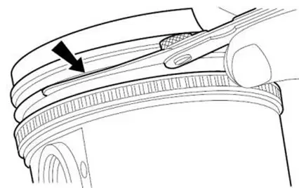
The figure shows how to use the feeler gauge to measure piston ring :
Diameter
Thickness
Side clearance
Width
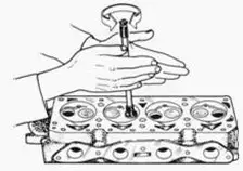
The process shown in the figure is :
Cylinder head flatness check
Valve diameter measurement
Cylinder head cracks check
Valve lapping

The figure shows how to :
Remove piston from cylinder
Install piston oil ring
Install piston compression ring
Remove piston compression ring
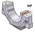
The purpose of the bearing NIP shown in the figure is to :
Prevent bearing from rotating
Allow bearing to rotate
Prevent bearing miss-assembly
Allow bearing miss-assembly
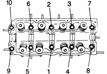
The figure shows the correct sequence of :
Loosening cylinder head bolts
Loosening crankshaft bolts
Tightening crankshaft bolts
Tightening cylinder head bolts
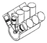
The type of cylinder arrangement shown in the figure is :
V-type
W- type
Opposed type
In-line type
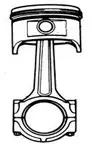
The figure shows the engine :
Piston assembly
Crankshaft assembly
Camshaft assembly
Cylinder head assembly

