
 Worksheets
Mech 1340 Quiz 2 Review
Total questions: 56
Worksheet time: 14hrs 0mins
The decimal system uses the number 9 as its base.
True
False
All digital computing devices perform operations in binary.
True
False
The base of a number system determines the total number of unique symbols used by that system.
True
False
In any number system, the position of a digit that represents part of the number has a weighted value associated with it.
True
False
Usually a group of 8 bits is a byte, and a group of one or more bytes is a word.
True
False
To express a number in binary requires fewer digits than in the decimal system.
True
False
In the Gray code there is a maximum of one bit change between two consecutive numbers.
True
False
Binary number systems use positive and negative symbols to represent the polarity of a number.
True
False
Normally, a binary 1 represents the presence of a signal, while a binary 0 represents the absence of a signal.
True
False
All inputs to an AND gate must be 1 to produce a 1 output.
True
False
All inputs to a NAND gate must be 1 to produce a 1 output.
True
False
Only one input to an OR gate must be 1 to produce a 1 output.
True
False
All inputs to a NOR gate must be 1 to produce a 1 output.
True
False
The AND function, implemented using switches, will mean switches connected in parallel.
True
False
A two input OR function, expressed as a Boolean equation, would be Y= AB.
True
False
Hardwired logic is fixed and is changeable only by altering the way devices are connected.
True
False
Programmable control is based on logic functions that are programmable and easily changed.
True
False
There is no difference between a relay schematic and a ladder logic program.
True
False
One of the most common PLC programming languages is ladder logic.
True
False
Ladder logic is a graphical representation of a user program.
True
False
In any number system, the position of a digit that represents part of the number has a "weight" associated with its value. The place weights for binary:
start with 1 and are successive powers of 2.
increase by adding 2 for each place, starting with 0.
increase by adding 2 for each place, starting with 2.
start with 2 and double for each successive place.
The number 12 is:
12 in any number system.
12 in decimal.
12 in binary.
all of the above.
The octal number 153 would be written in binary as:
011 101 001
001 101 011
011 111 101
010 100 011
The decimal number 28 would be written in binary as:
11100
00111
10110
01011
The hexadecimal number 2D9 would be written in binary as:
0010 1101 1001
1001 1011 0010
1100 1111 0010
0010 1011 1001
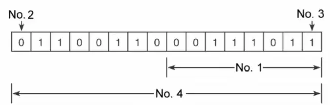
One byte of the data shown is represented by:
No.1
No.2
No.3
No.4
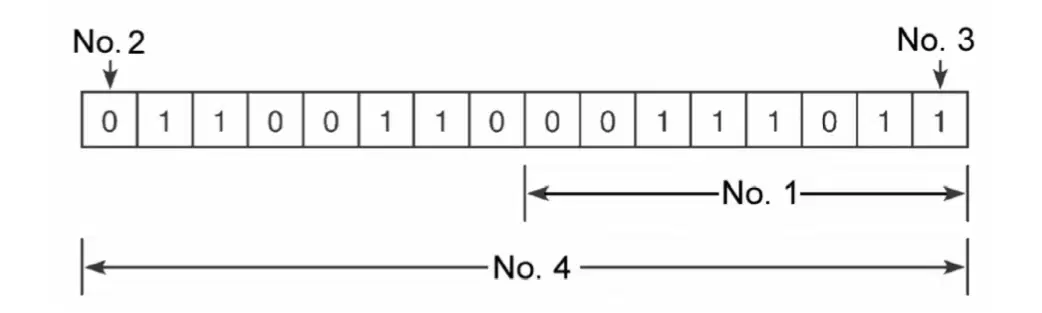
The MSB of the data shown in Figure 3-1 is represented by:
No.1
No.2
No.3
No.4
The acronym BCD stands for:
binary-coded decimal.
binary code decoder.
base code decoder.
base-coded decimal.
For a base 8 number system, the weight value associated with the third digit would be:
16
32
64
512
In the sign bit position, a 1 indicates a(n):
negative number.
positive number.
octal code.
hexadecimal code.
The 2's complement form of a binary number is the binary number that results when:
all the 1's are changed to 0's
all the 0's are changed to 1's.
1 is added to the 1's complement.
both a and b
A(n) _________ bit is used to detect errors that may occur while a word is moved
parity
negative
positive
overflow
The binary concept makes use of the fact that certain informal
can exist in one of two possible states.
can be broken down into smaller units for easier analysis.
can be divided into two or more categories.
can be divided into two, or multiples of two, categories.
The basic rule for an AND gate is:
if all inputs are 1, the output will be 1
if all inputs are 1, the output will be 0.
if all inputs are 0, the output will be 1.
both a and b.
The basic rule for an OR gate is:
if one or more inputs are 1, the output is 1.
if one or more inputs are 1, output is 0.
if one or more inputs are 0, the output is 1.
both band c.
The NOT function can be thought of as:
a FALSE-to-TRUE converter
a changer of states.
an inverter
all of these.
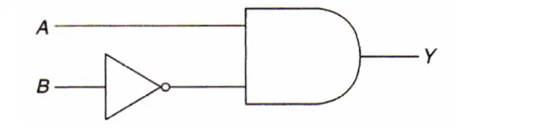
With reference to the logic circuit, the output Y will be at logic 1 when:
inputs A and B are logic 1.
input A or B is logic 1.
input A is at logic 1 and input B is at logic 0.
input A is at logic 0 and input B is at logic 1.
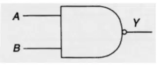
The logic symbol drawn in that of the:
AND Function
OR function
NOR function
NAND function
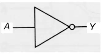
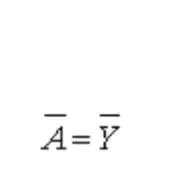
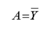
The Boolean equation for the logic symbol is:
A=Y
A=B
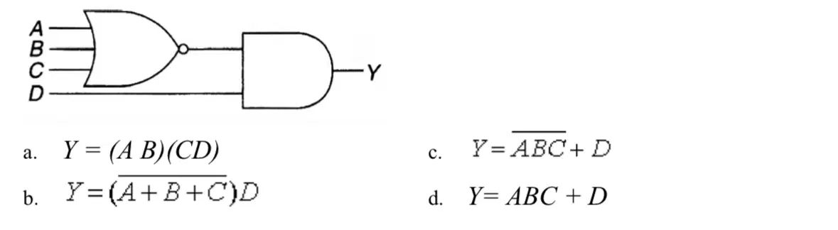
The Boolean expression for the logic circuit drawn in is:
A
B
C
D
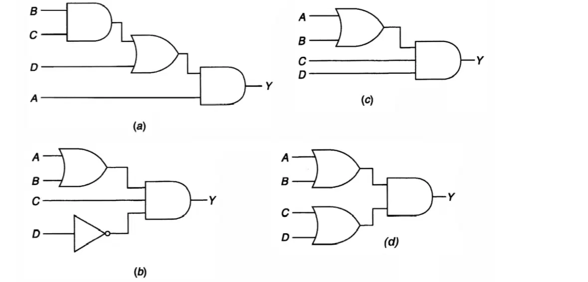
Which logic circuit represents the Boolean expressionY= A(BC+D)
A
B
C
D

Which of the hardwired relay schematics of is being implemented by the PLC program show?
A
B
C
D
A OR gate operates on the same principle as:
a series circuit.
a parallel circuit.
a series-parallel circuit
none of these.
A NOR gate is:
an AND gate with an inverter connected to the output.
an OR gate with an inverter connected to the output.
equivalent to a series circuit
equivalent to a parallel circuit
If you want to know when one or both matching bits in two different words are ON, you would use the logic instruction
AND
XOR
OR
NOT
Convert the binary number to a decimal number:
1111110
(a)
Convert the binary number to a decimal number:
10000000
(a)
Convert the decimal number to a binary number:
20
(a)
Convert the decimal number to a binary number:
17
(a)
Convert the Octal number to a binary number:
74
(a)
Convert the decimal number to BCD:
99
(a)
What is the 1s complement of 1001101?
(a)
Simplify, answer must be in binary.
100 +101
(a)
Simplify, answer must be in binary. 1110 - 0111
(a)
Answer must be in binary. 100 x 101
(a)
Answer must be in binary. 10100 ÷ 10
(a)

