
 Worksheets
Quiz on GD&T
Total questions: 30
Worksheet time: 23mins
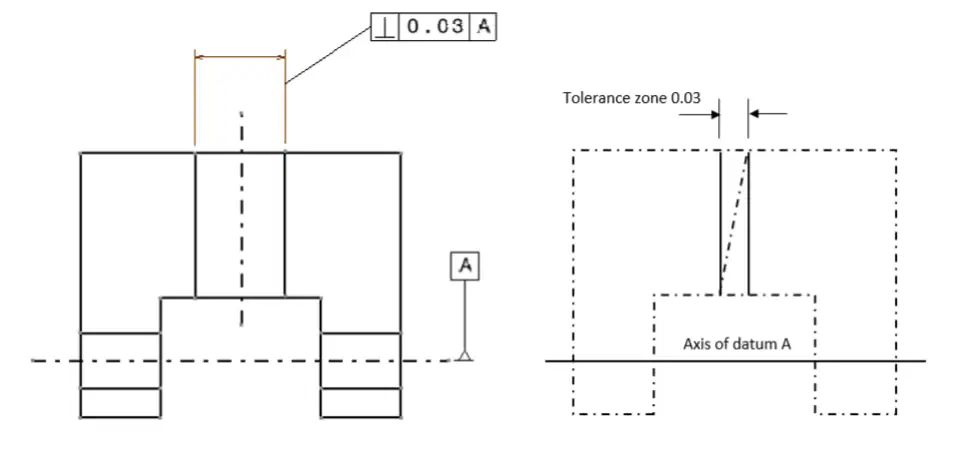
What does Figure 1 demonstrate in terms of squareness?
Squareness of an axis line with regards to a datum axis.
Squareness of a surface with respect to a datum plane.
Squareness of a circle with respect to a datum point.
Squareness of a cube with respect to a datum line.
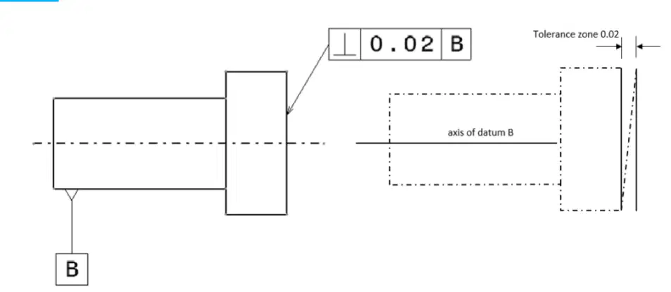
What is the tolerance zone defined as in the example provided?
Two hypothetical parallel planes separated by 0.02 unit distance
A single plane parallel to the axis of datum B
Two intersecting planes at 0.02 unit distance
A cylindrical zone around the axis of datum B
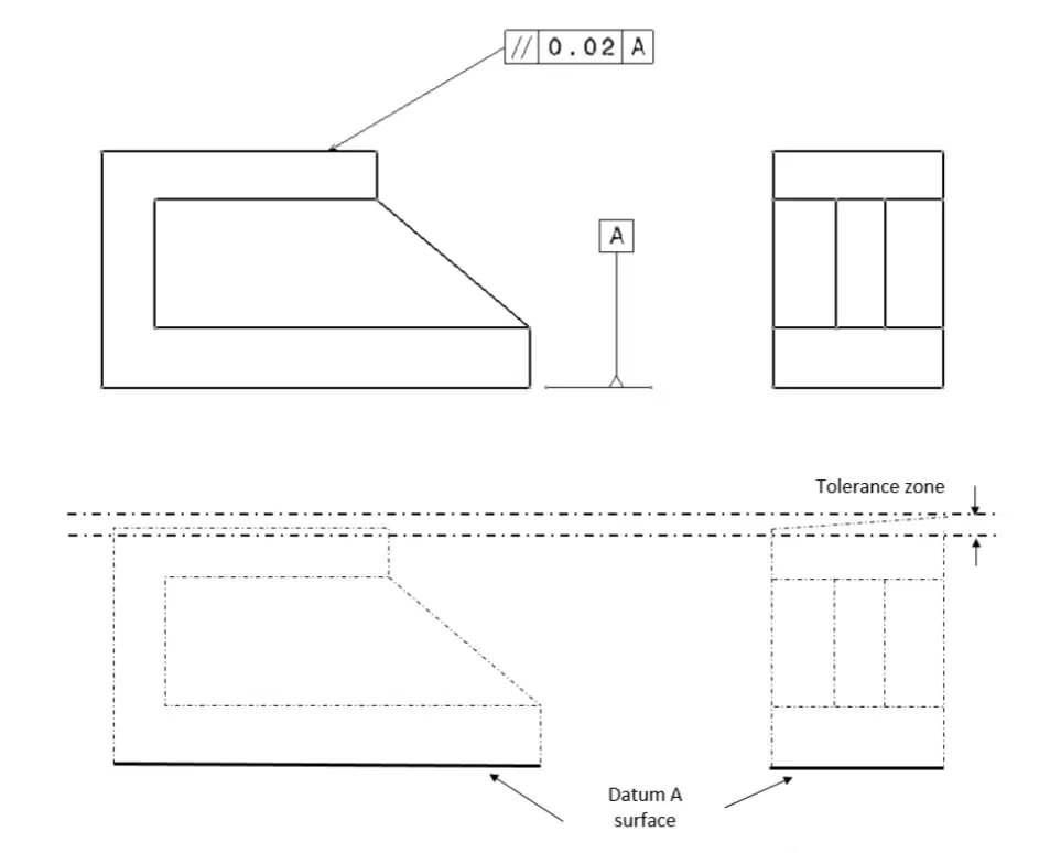
What is the tolerance zone for parallelism as described in the document?
Two parallel planes separated by 0.02
Two perpendicular planes separated by 0.02
Two parallel planes separated by 0.05
Two perpendicular planes separated by 0.05
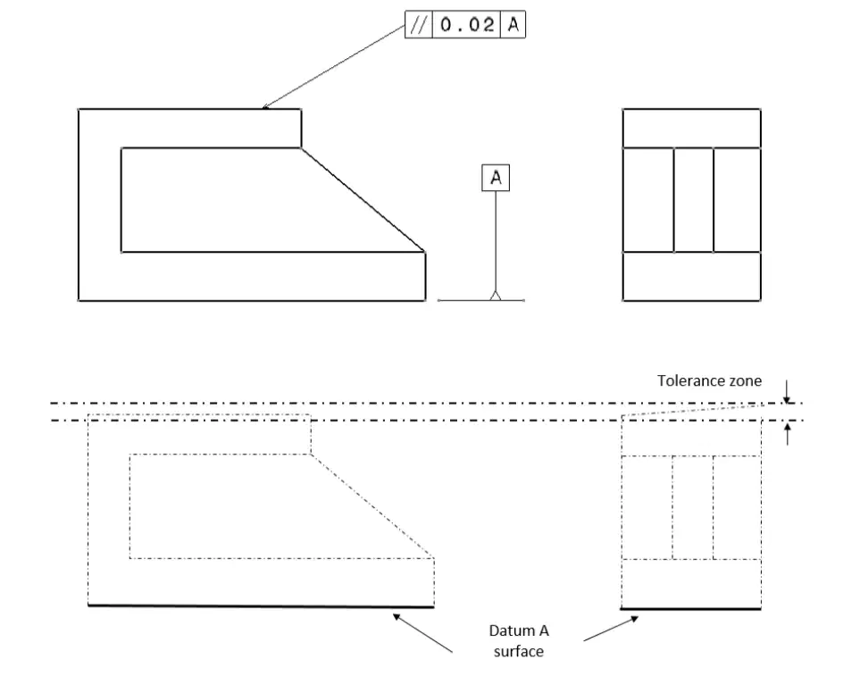
In the context of the document, what is the role of datum A?
It serves as a reference surface for parallelism
It is the surface to be measured
It is the tolerance zone
It is the surface to be ignored
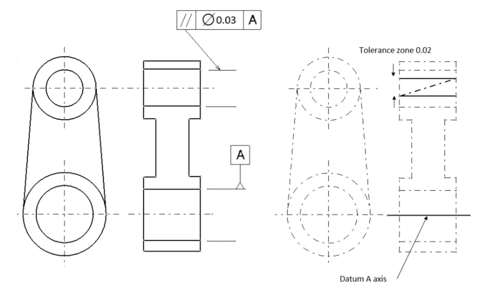
What is the diameter of the cylindrical tolerance zone for the axis of the pointed hole in the example of parallelism?
0.03
0.02
0.05
0.01
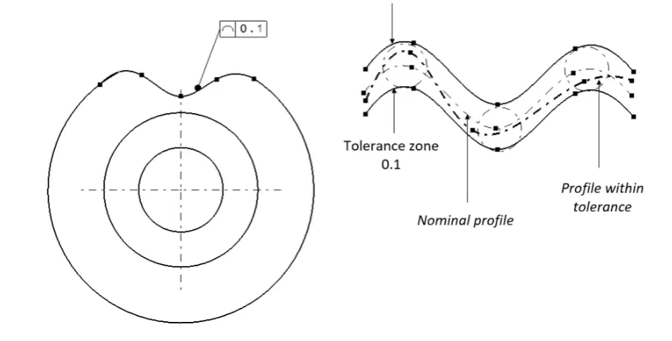
What is the unit distance for the tolerance zone in the line profile?
0.5
0.2
0.1
0.3
What type of tolerance does not require any datum in surface profile tolerancing?
Positional tolerance
Form tolerance
Angular tolerance
Size tolerance
Which tool is commonly used to measure the curved surface in surface profile tolerancing?
Vernier caliper
Coordinate measuring machine (CMM)
Micrometer
Ruler
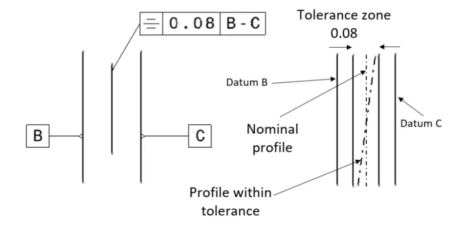
What is the maximum distance between the two parallel lines in the symmetry tolerance example shown in figure 7?
0.05
0.08
0.10
0.12

What is the separation distance between the two parallel lines in the symmetry tolerance example?
0.03
0.05
0.10
0.15
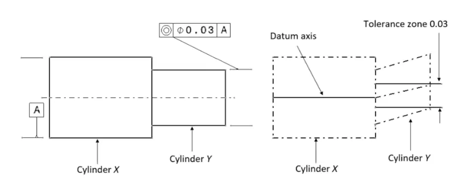
What is the diameter of the tolerance zone for the concentricity of an axis as shown in Figure 9?
0.03
0.05
0.01
0.07
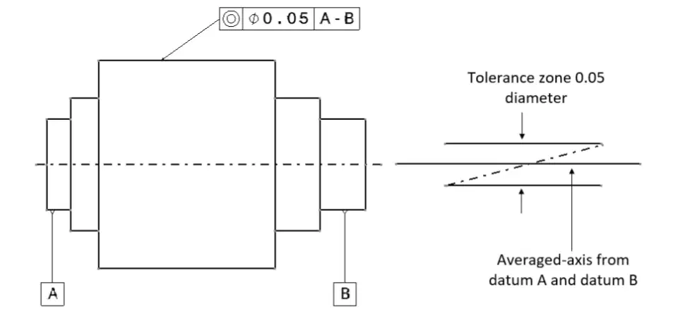
What is the diameter of the tolerance zone for the pointed cylinder in the drawing?
0.05
0.10
0.15
0.20
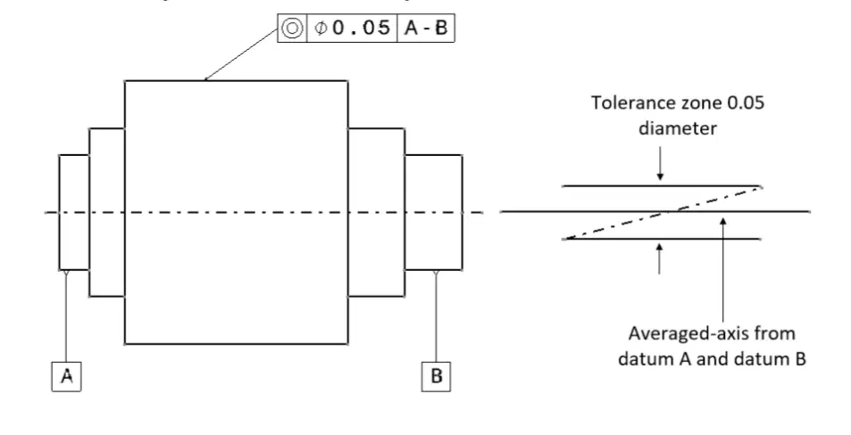
The axis of the pointed cylinder should be co-axial with which of the following?
Datum A cylinder only
Datum B cylinder only
Averaged-axis of datum A and datum B cylinders
Neither datum A nor datum B
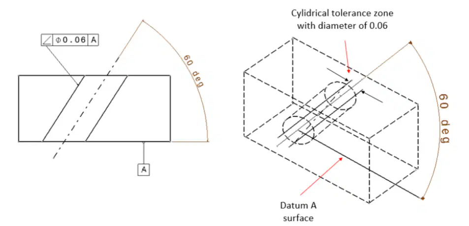
What is the orientation of the cylindrical tolerance zone with respect to the surface of datum A?
60 degrees
45 degrees
90 degrees
30 degrees
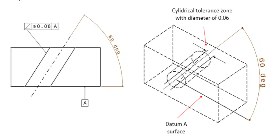
What is the diameter of the cylindrical tolerance zone?
0.06
0.10
0.08
0.04
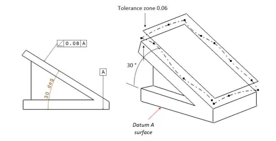
What is the tolerance zone for the pointed surface on the technical drawing?
Two parallel planes separated by 0.08 unit distance
Two parallel planes separated by 0.06 unit distance
Two parallel planes separated by 0.10 unit distance
Two parallel planes separated by 0.12 unit distance
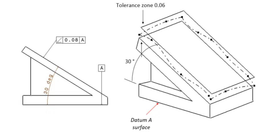
At what angle should the two parallel planes be oriented with respect to datum A surface?
45 degrees
60 degrees
30 degrees
90 degrees
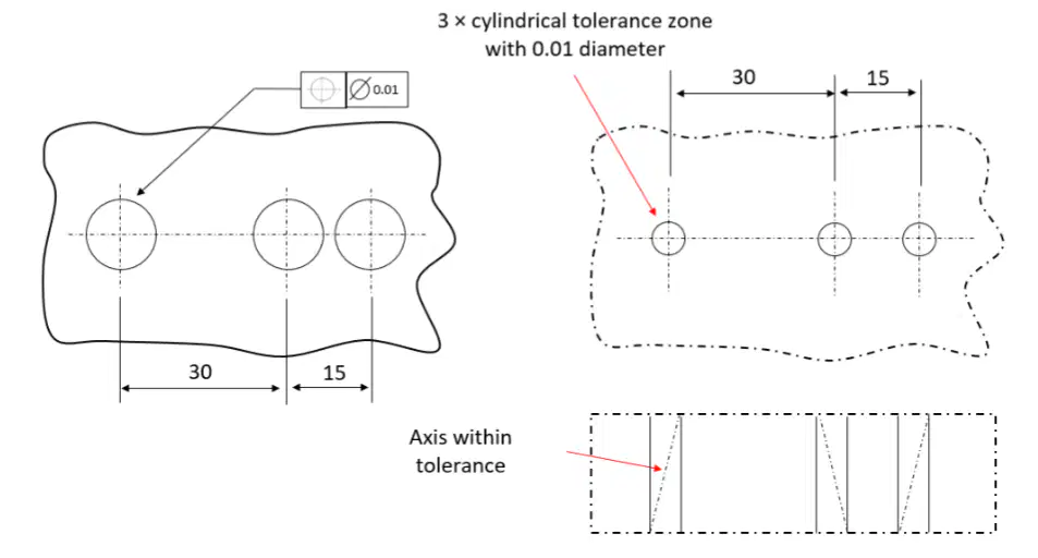
What is the diameter of the cylindrical tolerance zone mentioned in the explanation of position tolerance in figure 13?
0.01 unit distance
0.1 unit distance
1.0 unit distance
10 unit distance
In the explanation of position tolerance, how should the axis of the cylindrical tolerance zone be aligned with the other two cylinders?
Perpendicular
Parallel
Diagonal
Random
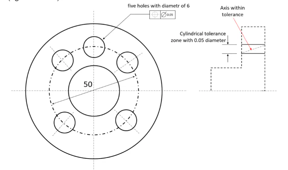
What does the position/location tolerance symbol in a technical drawing inherently refer to?
A dimension
A datum
A material
A color
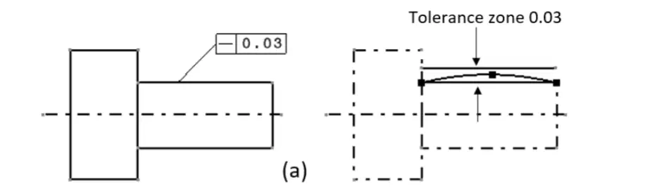
What is the tolerance zone for the straightness of the pointed cylindrical surface in figure 15a?
Two parallel lines separated by 0.03 unit distance
Two parallel lines separated by 0.05 unit distance
Two parallel lines separated by 0.01 unit distance
Two parallel lines separated by 0.1 unit distance
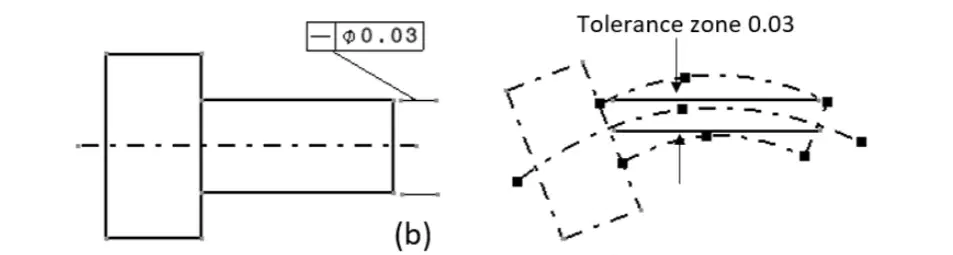
How is the straightness of the pointed axis of the small cylinder measured in figure 15b?
By taking points of profile lines by a CMM
By using a ruler
By visual inspection
By using a protractor
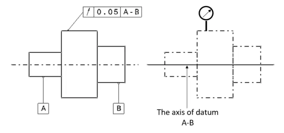
What does the run-out tolerance require for the cylinders in figure 16?
Roundness, concentricity, and parallelism tolerances
Only roundness tolerance
Only concentricity tolerance
Only parallelism tolerance
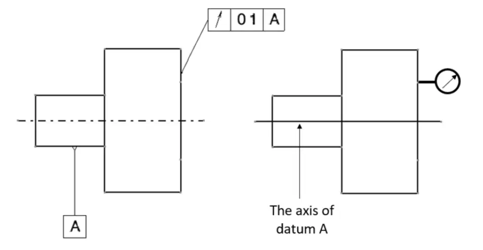
What is the maximum total movement of the indicator pointer of the dial-gauge for the pointed cylinder in figure 16 when rotated 360 degrees?
0.05
0.10
0.15
0.20
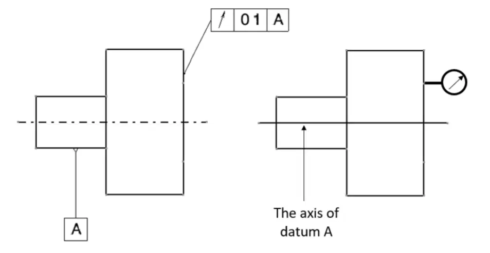
In figure 17, what must all cylinders satisfy in addition to run-out tolerance?
Squareness and flatness tolerances
Roundness and straightness tolerances
Parallelism and perpendicularity tolerances
Concentricity and symmetry tolerances
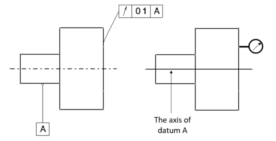
What is the maximum total movement of the indicator pointer of the dial-gauge for any points on the plane from the center point of the pointed surface in figure 17?
0.05
0.10
0.15
0.20
What does GD&T stand for in the context of engineering?
Geometric Dimensioning and Tolerancing
General Design and Tolerancing
Graphical Design and Tolerancing
Geometric Design and Testing
What is the purpose of using GD&T in engineering?
To represent geometrical relationships and complement traditional dimensional tolerance
To increase the size of components
To reduce the cost of materials
To simplify the design process
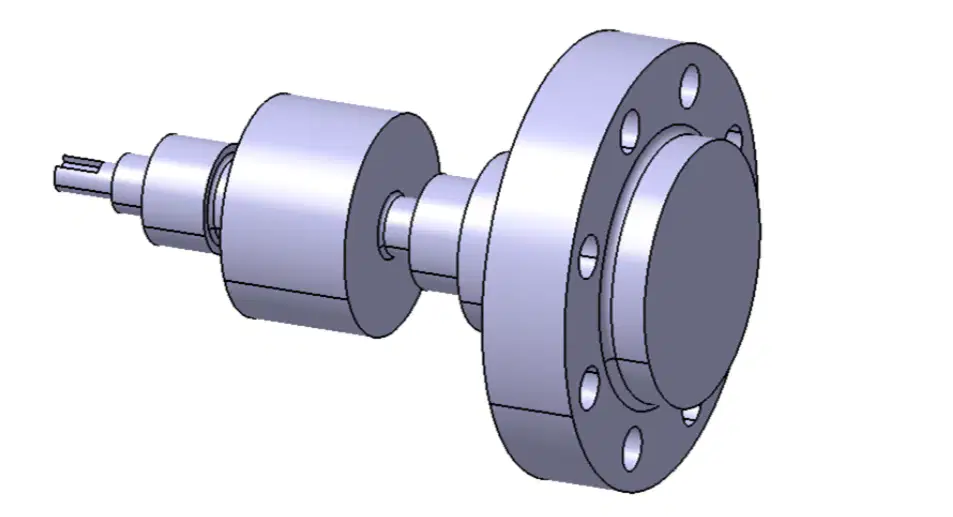
What feature is mentioned as being present at the end of the shaft with the smallest diameter?
A slot feature (keyway)
A cylindrical feature
A hole feature
A flat surface
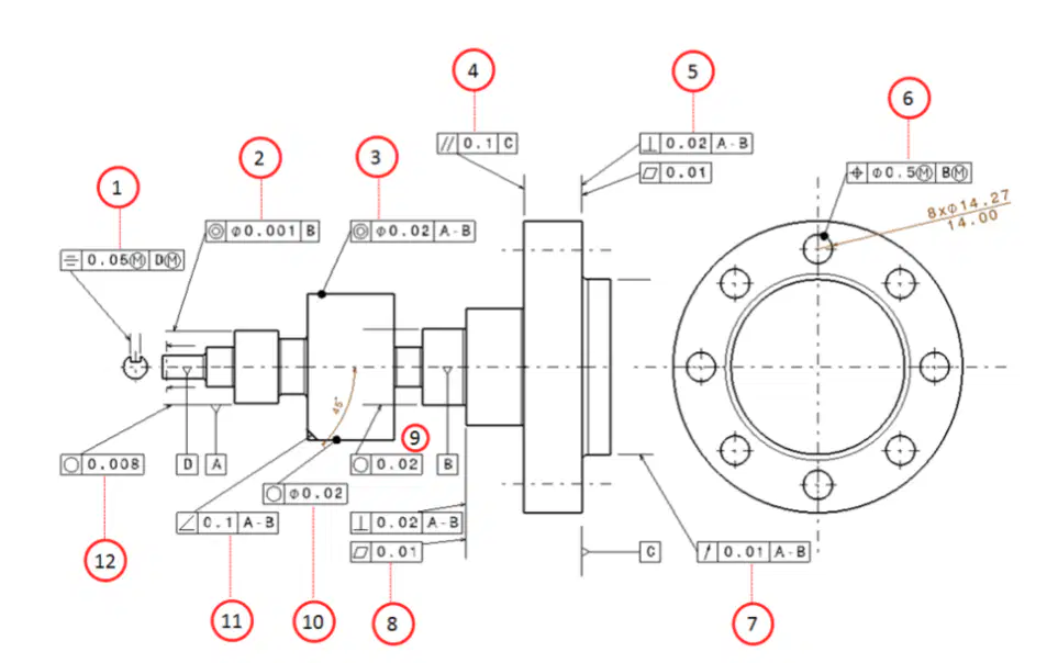
What does Figure 19 in the document primarily show?
2D technical drawing of a shaft with GD&T tolerances
3D model of a mechanical component
Electrical circuit diagram
Blueprint of a building

