
 Worksheets
Mech 1340 Final Pictures
Total questions: 46
Worksheet time: 12hrs 30mins
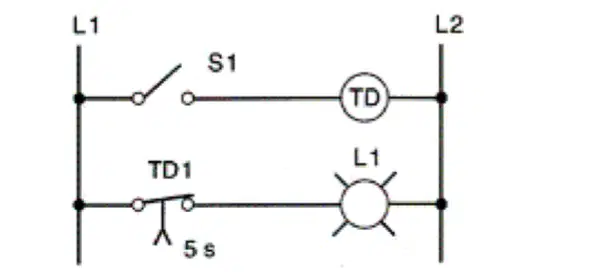
In the hardwired circuit shown, the light will stay on:
as long as S1 is closed
for 5 s after coil TD is energized.
for 5 s after coil TD is de-energized.
both a and c.
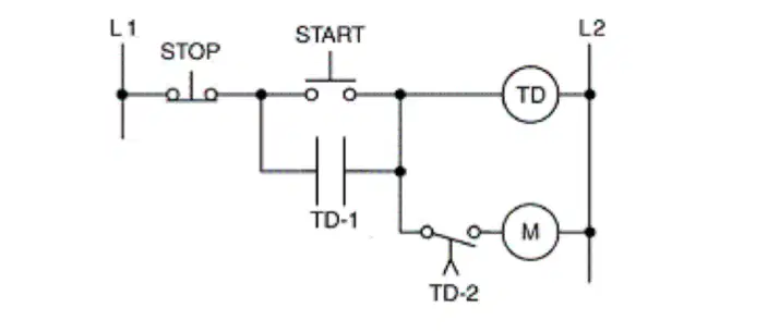
For the hardwired timer circuit shown, contact TD-1 is the ____ contact and TD-2 is the ____ contact.
ON, OFF
OFF, ON
instantaneous, timed
timed, instantaneous

For the programmed timer circuit shown, assume the switch is closed for 5 seconds and than opened. After 12 seconds have elapsed motor(s) ____ will still be operating.
M1, M2, M3
M2, M3
M3
none of these
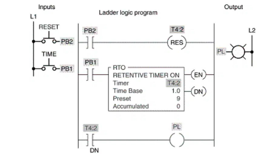
For the program shown, the timer starts timing when:
PB1 is closed.
PB2 is closed.
both PB1 and PB2 are closed.
either PB1 or PB2 is closed.
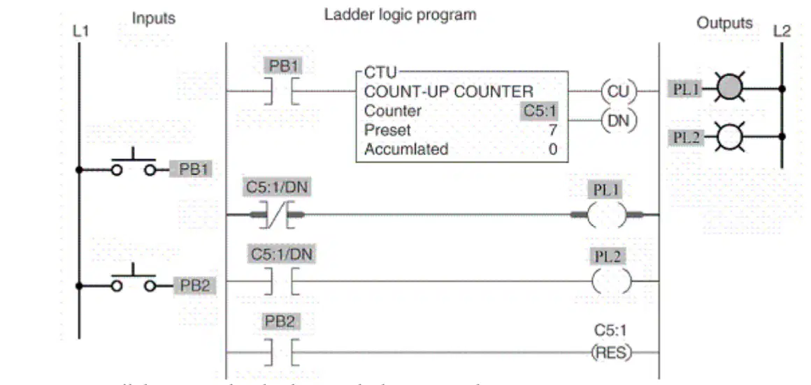
Output PL2 will be energized:
until the accumulated value equals the preset value.
when the accumulated value equals the preset value.
only when the accumulated value exceeds 10.
only when the accumulated value is zero.
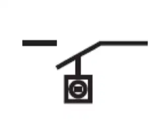
?
Limit Switch
Temperature Switch
Level Switch
Pressure Switch

?
Coil
N.C. Contact
N.O. Contact
Lamp
?
Socket
Single Phase Motor
Plug
Plug and Socket
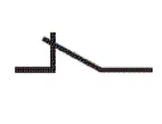
?
N.O. Contact
Coil
N.C. Contact
Lamp
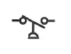
?
Temperature Switch
Pressure Switch
Level Switch
Limit Switch
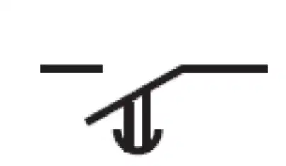
?
N.C. Contact Delay Opening
N.O. Contact Delay Closing
N.C. Contact Delay Closing
N.O. Contact Delay Opening
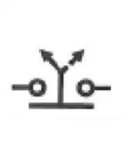
?
Three Position Selector Switch
N.O. Push Button
N.C. Push Button
Two Position Selector Switch
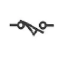
The symbol shown is that for a:
Pressure Switch
Temperature Switch
Limit Switch
Level Switch
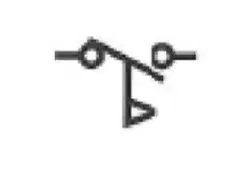
?
Flow Switch
Emergency Stop Button
Proximity Sensor
Solenoid Coil
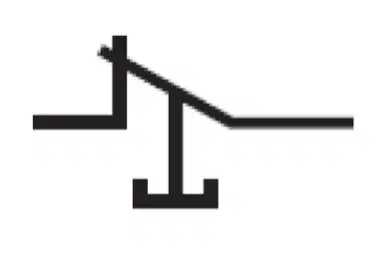
?
N.C. Push Button
N.O. Push Button
Two Position Selector Switch
Three Position Selector Switch
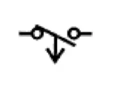
?
N.C. Contact Delay Opening
N.O. Contact Delay Closing
N.C. Contact Delay Closing
N.O. Contact Delay Opening
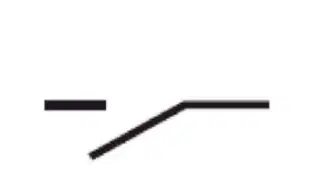
?
Lamp
N.C. Contact
N.O. Contact
Coil
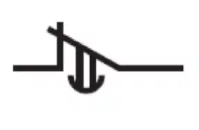
?
N.O. Contact Delay Opening
N.C. Contact Delay Closing
N.O. Contact Delay Closing
N.C. Contact Delay Opening
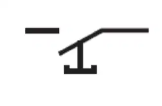
?
Three Position Selector Switch
N.C. Push Button
N.O. Push Button
Two Position Selector Switch

?
Solenoid Coil
Emergency Stop Button
Flow Switch
Proximity Sensor
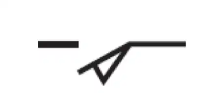
?
Temperature Switch
Level Switch
Limit Switch
Pressure Switch

?
Two Position Selector Switch
N.O. Push Button
Three Position Selector Switch
N.C. Push Button
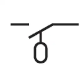
?
Level Switch
Limit Switch
Pressure Switch
Temperature Switch

?
Proximity Sensor
Flow Switch
Solenoid Coil
Emergency Stop Button

?
Three Position Selector Switch
N.O. Push Button
N.C. Push Button
Two Position Selector Switch
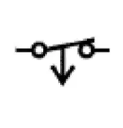
?
N.O. Contact Delay Opening
N.C. Contact Delay Opening
N.C. Contact Delay Closing
N.O. Contact Delay Closing
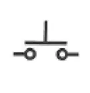
?
N.C. Push Button
N.O. Push Button
Three Position Selector Switch
Two Position Selector Switch
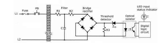
The schematic diagram shown is that of a(n):
discrete input module
analog output module
discrete output module.
analog input module
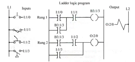
The instruction at address B3:1/3 is associated with:
an internal relay coil.
an external input device.
an external output device.
the solenoid.
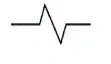
The symbol shown is that for a:
solenoid
motor
heater
horn
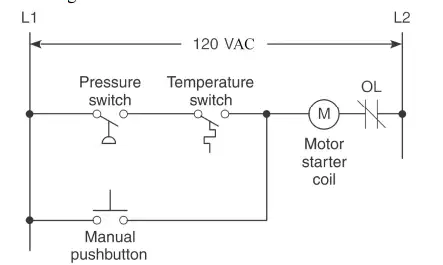
The diagram shown is that of a
hardwired relay schematic
input module schematic
ladder logic program.
output module schematic.
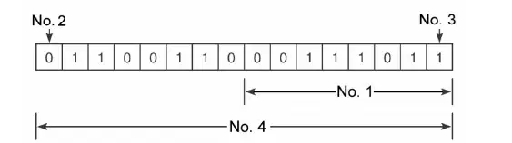
One byte of the data shown is represented by:
No. 1
No. 4
No. 2
No. 3
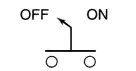
The device represented by the symbol is a:
drum switch.
sequence switch.
selector switch.
toggle switch.
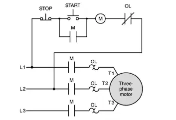
The motor starter coil M is:
part of the power circuit.
energized to start the motor.
energized only as long as the start button is pressed.
all of the above.
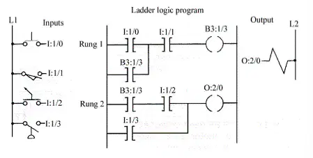
For the program shown, what is the address of the instruction associated with the pressure switch?
I:1/1
I:1/2
I:1/3
I:1/0
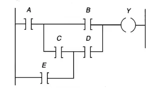
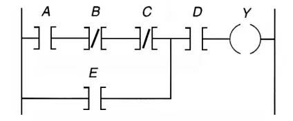
The Boolean equation for the logic represented in the ladder diagram can be expressed as:
Y = (AB) + (ACD) + (DE) + (BCE)
Y = (AB) + (AC) + (AD) + (ED)
Y= (AB) + (CD) + E
Y = (AB) + (ACD) + (DE)
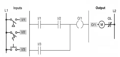
For there to be is a continuous logic path from left to right across the rung:
I/1, 1/2, and 1/3 must all be at logic 1
I/1 and 1/2 or 1/3 will be at logic 0.
I/1 and 1/2 or 1/3 must be at logic 1
I/1, 1/2, and 1/3 must all be at logic 0.
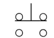
The pushbutton symbol shown, would be classified as a(n):
ON/OFF pushbutton.
NC pushbutton.
break-before-make pushbutton.
NO pushbutton.
For the program shown, instruction A represents an:
Output Energize instruction
Examine If Closed instruction.
Examine If Open instruction.
Input Energize instruction.
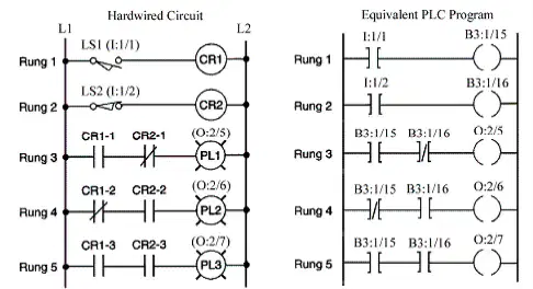
When both LS1 and LS2 are not actuated:
PLC program rung 1 is False.
PLC program rung 2 is True.
pilot light PL2 (O:2/6) is ON.
all of these.
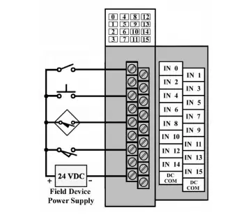
The devices connected to the terminals would be classified as:
internal output instructions
field input devices.
field output devices
internal input instructions.
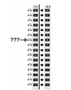
The address for the point on the I/O module shown would be:
I:6/1
O:1/6
O:6/1
I:1/6
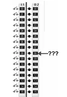
The address for the point on the I/O module would be:
I:2/8
O:8/2
O:2/8
I:8/2
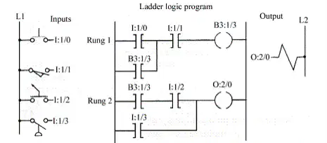
Rung 2 will be True whenever:
the pressure switch is closed.
the pushbutton is closed.
the selector switch is closed and rung 1 is True.
either a or c.
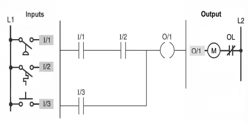
The diagram shown is that of a:
ladder logic program.
relay schematic.
input module wiring diagram
output module wiring diagram
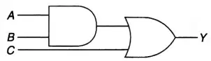
The Boolean expression for the logic circuit drawn is:
Y=A+B+C
Y = ABC
Y=AB+C
Y = (A + B)C

