
 Worksheets
Electrical Circuit Theory - MCQ
Total questions: 120
Worksheet time: 3600secs
In a parallel circuit, removing one resistor will
Not affect total resistance
Cause a short circuit
Decrease total resistance
Increase total resistance
In KCL the algebraic sum of all currents entering and leaving at a Node is
Equal to the supply voltage
Equal to the resistance
Equal to one
Equal to Zero
Kirchoff's Voltage Law (KVL) is based on which fundamental principle?
Conservation of charge
Conservation of energy
Law of resistance
Newton's law
In a parallel circuit, the voltage across each branch is
Zero
Same
Different
Half of the total voltage
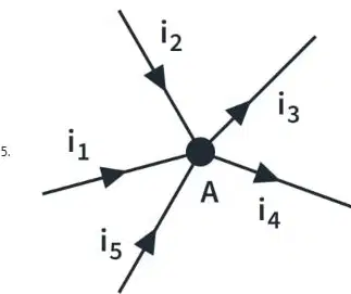
In the above circuit diagram, if the values of i1=5A, i2=3A, i3=4A and i4=6A, Then what is the value of i5?
1A
2A
3A
4A
According to Kirchhoff's Voltage Law (KVL), the sum of voltages around any closed loop in a circuit is
Equal to Zero
Equal to the total Resistance
Equal to the total current
Equal to one
If the voltage across a resistor is 10V and the current through it is 2A, what is the value of resistance?
5 ohms
2 ohms
20 ohms
0.2 ohms
In a circuit, if one of the resistor in series burns out, the entire circuit will
Stop working
Short circuit
Continue working normally
Work at half power
The Delta-Star transformation is used to simplify
Series circuit
Parallel circuit
Three terminal networks
Series Parallel circuit
Which of the following statements is true according to Ohm’s Law?
Voltage is inversely proportional to current
Resistance increases with current
Voltage is directly proportional to current
Current is independent of voltage
If all resistors in the star network are equal to R, the equivalent delta resistors will be
R/2
2R
2R
3R
In a series circuit, the current
Is zero
Depends on the voltage only
Splits equally among components
is same through all components
A 60 W bulb and a 100 W bulb are connected in series. Which bulb glows brighter?
60 W
100 W
Both equally
Depends on supply voltage
How many mesh equations are required for a circuit with 'n' meshes?
n+1
n-1
n
1
What is the total value of resistance if three resistors of 2 Ω, 4 Ω, and 6 Ω are connected in series?
1 Ω
6 Ω
2 Ω
12 Ω
Matrix equation for Node voltage analysis is
[R][V]=[I]
[R][I]=[V]
[G][V]=[I]
[G][I]=[V]
17. Kirchoff’s Current Law (KCL) is based on the law of conservation of
Charge
Energy
Mass
Momentum
Matrix equation for mesh current analysis is
[R]*[V]=[I]
[R]*[I]=[V]
[G]*[I]=[V]
[G]*[V]=[I]
Which of the following equation Explain the Ohms law
V=I.R
I=V.R
R=VI
V=I/R
Three resistors of 4 Ω, 6 Ω, and 12 Ω are connected in parallel. What is the total value of resistance?
2 Ω
2 kΩ
1 Ω
3 Ω
When finding Thevenin resistance (Rth), what do we do with a current source?
It is left as-is
It is replaced by an open circuit
It is replaced by a voltage source
It is replaced by a short circuit
If the Thevenin resistance is 5 Ω and Thevenin voltage is 10 V, the current through a 5 Ω load is
0.5 A
1 A
2 A
5 A
The Thevenin equivalent circuit consists of
A single current source and a parallel resistor
A single voltage source and a series resistor
A single voltage source and a parallel resistor
A single current source and a series resistor
The Thevenin equivalent voltage is measured across
The terminals where the load is connected
The terminals where the voltage source is connected
The entire circuit
The terminals where the current source is connected
The Norton equivalent circuit consists of
A voltage source in series with a resistor
A voltage source in series with a resistor
A current source in parallel with a resistor
A current source in parallel with a resistor
The efficiency of power transfer under maximum power condition is
25%
50%
75%
The superposition theorem is applicable to
Linear circuits only
Non-linear circuits only
Both linear and non-linear circuits
Passive circuits only
Norton's theorem CANNOT be applied to
Non-linear circuits
Circuits with resistors and sources
Circuits with capacitors and inductors
Circuits with both AC and DC sources
Thevenin's voltage is
The open-circuit voltage across the load terminals
The short-circuit current across the terminals
The voltage when the circuit is loaded
The voltage drop across the internal resistance
In a DC circuit, Maximum power is transferred to the load when
Load resistance is zero
Load resistance equals source resistance
Load voltage equals source voltage
Load resistance is infinite
Superposition theorem is NOT applicable to
Circuits with only resistors
Circuits with linear elements
Circuits with Diodes
Circuits with more than two sources
The Norton equivalent circuit is obtained by
Calculating maximum power delivered to the load
Finding the open-circuit current and equivalent resistance
Finding the open-circuit voltage and equivalent resistance
Finding the short-circuit current and equivalent resistance
In DC circuits, maximum power transfer occurs when (RL- Load Resistance, Rth - Thevenin Resistance)
RL = Rth
RL > Rth
RL < Rth
RL = 0
When applying the superposition theorem to a circuit with multiple independent sources, the total response is the
Product of individual responses
Sum of individual responses
Average of individual responses
Maximum of individual responses
Thevenin's and Norton's theorems are
Not related
Mathematically equivalent
Only used in AC analysis
Applicable to non linear circuits
In the maximum power transfer condition, the voltage across the load is
0%
50%
75%
100%
The load in a circuit is:
Equal to the source voltage
Twice the source voltage
Half the source voltage
Zero
Which of the following elements violates the assumptions of the superposition theorem?
Capacitor
Resistor
Inductor
Diode
What is the main advantage of Thevenin's theorem?
Increases current in the circuit
Simplifies analysis of power systems
Eliminates the need for resistors
Works only in DC circuits not in AC circuits
A voltage source has an internal resistance of 5Ω. For maximum power transfer, what should be the load resistance value which should be connected to that voltage source?
0 Ω
25 Ω
10 Ω
5 Ω
A circuit has a Thevenin voltage of 12 V and a Thevenin resistance of 4 Ω. The Norton current is
12 A
48 A
170 A
4 A
Time period of 50 Hz AC supply is
0.0002 Second
0.02 Second
0.2 Second
2 Second
If Vrms = 120 V, what is the value of Vpeak?
70.7 V
141.4 V
170 V
60 V
For a sinusoidal waveform, the peak factor is
1.732
1.414
0.5
1.11
Form Factor is defined as
Ratio of RMS value to Average value
Ratio of Average value to RMS value
Ratio of Maximum value to RMS value
Ratio of RMS value to Maximum value
In a pure inductive circuit, the current
Leads the voltage by 90 degrees
Lags the voltage by 90 degrees
For a series RC circuit, increasing the frequency will
Increase capacitive reactance
Decrease capacitive reactance
Have no effect on reactance
Increase phase angle
What is the Apparent power in an AC circuit
Product of Average voltage and Average current
Product of peak voltage and peak current
Product of RMS voltage and RMS current
Sum of peak voltage and peak current
If V = 50 sin(100πt), what is the peak Voltage value?
25 V
50 V
75 V
100 V
What is the value of Active power in a purely inductive circuit?
Equal to Zero
Equal to one
Equal to Reactive power
Equal to Apparent power
If the average value of a sinusoidal voltage is 100 V, the peak value is
100 V
70.72 V
157 V
63.69 V
What is the value of Reactive power in a purely Resistive circuit?
Equal to apparent power
Equal to Active power
Equal to one
Equal to Zero
The Power Factor is defined as
the ratio between Reactive power to Apparent power
the ratio between Apparent power to Active power
the ratio between Reactive power to Reactive power
the ratio between Active power to Apparent power
In a pure resistive circuit, voltage and current are
Out of phase
In phase
90° apart
180° apart
Formula to find RMS value of a sine wave is
Vm / √2
Vm * √2
√2 * Vm
2 * Vm
The Power Triangle Represents
The relationship between voltage, current and resistance
The relationship between resistance, inductance and capacitance
The relationship between active power, reactive power and apparent power
The relationship between frequency, wavelength and speed
What will be the power factor of pure resistive circuit
0.0
0.5
0.866
In a series RLC circuit the power factor can be controlled by
Inductance value
Capacitance value
Frequency
All of the above
What is the power factor of pure inductive circuit
0.0
0.5
0.866
In a pure capacitive circuit, current
Leads voltage by 90 degree
Lags voltage by 90 degree
In phase with voltage
Lag relation with Voltage
For a series RL circuit, increasing the frequency will
Increase inductive reactance
Decrease inductive reactance
Increase phase angle
Have no effect on reactance
Current at Resonance in a Parallel RLC circuit
Maximum
Minimum
Zero
Indeterminable
Voltage Magnification occurs in
Parallel resonance
Series resonance
RL circuit
Pure resistive circuit
Q factor in a parallel RLC circuit is given by
R / XL
XL / R
(1/R) * √(L/C)
L / R
At parallel resonance, impedance of an RLC circuit is equal to
XL
XC
L / CR
L / CR
5. In rectangular form, admittance is written as:
G + jB
R + jX
V + IR
Z + jY
If Q = 10 and R = 5 Ω, then XL = ?
50 Ω
0.5 Ω
2 Ω
10 Ω
Resonance occurs when
XL > XC
XL = XC
XC > XL
R = 0
Bandwidth is defined as
Current Range around resonance
Voltage range around resonance
Total impedance
Frequency range around resonance
The other name of series resonant circuit is
Current Magnifier circuit
Filter circuit
Rejector circuit
Acceptor circuit
Current magnification occurs in
Parallel resonance
Series resonance
RL circuit
Pure resistive circuit
Convert 10∠30° to rectangular form
5 + j5
8.66 + j5
10 + j10
7 + j7
Which of the following represents admittance (Y)?
VI
V / I
1 / Z
1 / Z²
The polar form of the complex number 3 + j4 is
5∠31.13°
7∠45°
4∠45°
5∠45°
If conductance is G and susceptance is B, then |Y| = ?
G² + B²
√(G² + B²)
(G² - B²)
G² - B²
The other name of parallel resonant circuit is
Filter circuit
Voltage Magnifier circuit
Acceptor circuit
Rejector circuit
Impedance at Resonance in a series RLC Circuit is
Minimum
Maximum
Zero
Indeterminable
At resonance, power factor is
Zero
Unity
Negative
Infinite
What is the unit of Admittance
Amperes
Volts
Mho
Ohm
In an RLC circuit, the voltage across an Inductor(L) at resonance is
Zero
Equal to voltage across R
I x XL
I x R
Selectivity in resonance circuit refers to
Voltage drop
Filtering ability
Capacitance value
Impedance value
In two wattmeter method, If the readings of two wattmeters are given as 1000W and 2000W then, what will be the value of total 3 phase power?
-1000 W
1000 W
3000 W
1500 W
In Delta connection, if the Line voltage is given as 173.2 V then the value of phase voltage will be
95.4 V
173.2 V
300 V
100 V
The relationship between line current (IL) and phase current (Iph) in a delta-connected system is
IL = √3 Iph
Iph = √3 IL
IL = 3 Iph
Iph = 3 IL
In a 3-phase system, If the values of Line voltage, Line current and power factor are 400 V, 10A and 0.8 then the value of 3 phase power will be
3200 W
4000 W
4800 W
6400 W
In DELTA connection, if the value of Phase current is 100 A then the value of Line current will be:
173.2 A
57.74 A
100 A
70.7 A
The relationship between line voltage VL and phase voltage Vph in a delta connected system is:
Vph = √3VL
VL = √3Vph
VL = 3Vph
VL = Vph
In two wattmeter method, If the power factor of three phase circuit is 0.5 then:
W1 = - W2
W1 = 0, W2 = Total power
W1 = 0.5 * W2
W1 = W2
In two wattmeter method, If the power factor of three phase circuit is Zero then:
W1 = - W2
W1 = 0, W2 = Total power
W1 = 0.5 * W2
W1 = W2
The total power in a balanced three phase system is given by:
P=√3 * VL * IL * COS θ
P= 3 * Vph * Iph * COS θ
P = W1 + W2 (W1, W2 - Readings of two wattmeters)
All of the above
A 3-phase delta connected load has each phase of 10 ohm. If the line voltage is 400 V, the phase current is:
23.1 A
40 A
11.5 A
40.5 A
In a 3-phase balanced system, If the values of phase voltage, phase current and power factor are 230 V, 10A and 0.8 then the value of 3 phase power will be:
3186.88 W
5520 W
1840 W
2000 W
In star connection, if the value of Line voltage is 173.2 V then the value of phase voltage will be:
400 V
300 V
200 V
100 V
In star connection, if the value of Phase current is 100 A then the value of Line current will be
173.2 A
57.74 A
100 A
70.71 A
The relationship between line voltage VL and phase voltage Vph in a star-connected 3 phase system is
Vph = √3 VL
VL = √3 Vph
VL = 3 Vph
Vph = VL
The relationship between line current (IL) and phase current (Iph) in a star connected system is
IL = √3 Iph
Iph = √3 IL
IL = 3 Iph
IL = Iph
In two wattmeter method, If the power factor of three phase circuit is Unity, then (W1-Reading of one wattmeter, W2-Reading of another wattmeter)
W1 = W2
W1 = 0, W2 = Total power
W1 = 0.5 * W2
W1 = W2
In two wattmeter method, If the power factor of three phase circuit is 0.866 then
W1 = W2
W1 = 0, W2 = Total power
W1 = 0.5 * W2
W1 = W2
What is the power factor in a balanced three-phase system?
The ratio of active power to apparent power
The sum of active power and apparent power
The product of active power and apparent power
The different between active power and apparent power
In a balanced three-phase system the phase voltages are
Different in magnitude and 60 degrees apart in phase
Different in magnitude and 120 degrees apart in phase
Equal in magnitude and 60 degrees apart in phase
Equal in magnitude and 120 degrees apart in phase
.The SI unit of resistance is
Ohm
) Farad
Henry
Watt
Ohm’s law states that
V ∝ I
V = I/R
) I = R/V
) I = VR
The power dissipated in a resistor is
R 2 I
IR
I²R
V²R
The total resistance of three resistors connected in series is
R₁R₂R₃
R₁ + R₂ + R₃
1/R₁ + 1/R₂ + 1/R₃
(R₁R₂)/(R₁ + R₂)
Thevenin’s theorem is applicable only to
AC networks only
AC networks only
Nonlinear networks
Linear networks
Norton’s equivalent circuit consists of
Voltage source in parallel with Thevenin’s resistance
Current source in parallel with Thevenin’s resistance
Voltage source in series with Thevenin’s resistance
Inductor in series with resistor
In superposition theorem, all other sources are replaced by
Open circuit for voltage, short circuit for current
Short circuit for voltage, open circuit for current
Both shorted
Both opened
Maximum power transfer occurs when load resistance equals
Source resistance
Half of source resistance
Twice source resistance
Twice source resistance
The average value of a pure sine wave is
0.707 × Vmax
0.637 × Vmax
1.11 × Vmax
Vmax
The RMS value of a sine wave is
0.707 × Vmax
0.5 × Vmax
1.11 × Vmax
0.637 × Vmax
In a pure inductive circuit, current
Lags voltage by 90°
Leads voltage by 90°
Is in phase
Is
opposite in phase
Power factor of a purely resistive circuit is
0
0.5
1 (Unity)
0.707
Resonance occurs when
XL = XC
XL > XC
XL < XC
R = XL
The unit of conductance is:
mho
Ohm
Watt
Henry
The Q-factor of a coil is the ratio of
Resistance to reactance
Reactance to resistance
Voltage to current
Power to frequency
In a two branch parallel circuit, the total admittance is equal to the:
difference of branch admittances
reciprocal of branch admittances
sum of branch admittances
ratio of branch admittances
In a delta-connected system
the line voltage is equal to the phase voltage
the phase voltage is equal to the line voltage
the line voltage is √3 times the phase voltage
the phase voltage is √3 times the line voltage
The phase sequence in a three-phase system determines
The magnitude of the phase voltages
The direction of rotation of motors
The line current
The efficiency of power transmission
In a balanced three-phase load, when the power factor is unity, the twowattmeter
method will result in:
Both wattmeters showing the same value
One wattmeter showing zero and the other showing the total power
Both wattmeters showing zero
Both wattmeters showing different values
Symmetrical components are primarily used to:
Simplify the analysis of unbalanced systems
Measure the total power in a system
Measure the impedance of the system
Analyze balanced systems

