
 Worksheets
British Standards — Graphics in Industry and Drawing Standards
Total questions: 55
Worksheet time: 28mins
Dimensioning is defined as the process of stating measurements on technical drawings to communicate between the design engineer and the manufacturer. What is the primary purpose of dimensioning?
To add decorative annotations to drawings
To communicate exact sizes and locations of features for manufacture
To identify the material specification only
To replace the need for views or projections
According to general principles for dimensioning, which statement is correct about units on technical drawings when millimetres are used?
Linear dimensions should be expressed in centimetres (cm) and include the unit symbol after every value.
All measurements should be in millimetres (mm); if mm is stated in the title block, omit the unit from individual dimensions.
Use inches unless otherwise instructed and always include the double-quote symbol.
The drawing must mix mm and cm to reduce errors.
Which practice correctly describes how to dimension a radius on arcs, curves, and rounded corners?
Use the symbol Ø and place it before the figure.
Use the letter R; the dimension line should pass through or inline with the arc centre and have a single arrowhead touching the arc.
Show two arrowheads and avoid touching the arc.
Do not indicate the arc centre when dimensioning radii.
When a complete circle is shown in a drawing, how should its size be stated?
By a radius using the letter R only
By a diameter using the symbol Ø placed in front of the figure
By the circumference measured along the outline
By a chord length taken from a datum
Figures on linear dimension lines should be placed so that they can be read from either the bottom or the right-hand side of the drawing. Which placement rule also applies to these figures?
Figures should touch outlines and centre lines.
Figures should not touch outlines, dimension lines, or centre lines; use a comma for decimals where required.
Figures must be oriented vertically regardless of the drawing.
Figures should be hidden to avoid clutter.
Intermediate dimensions that give sizes for individual parts of a drawing arranged one after the other are known as chain dimensioning. What is the main characteristic of chain dimensioning in this context?
Dimensions radiate from a common datum edge.
Dimensions are listed sequentially, each continuing from the previous size.
Only overall size is given outside all other dimensions.
Dimensions are shown only as angles.
Multiple dimensions taken from a datum line and set out parallel to each other illustrate parallel dimensioning. Which description matches this method?
All dimensions continue one after another with no common origin.
Dimensions originate from a common reference and are parallel to each other.
Only the largest dimension is shown outside the view.
Dimensions are shown as diameters only.
Overall dimension lines give the maximum sizes of objects (total length and total height) and should be placed outside all other dimensions. What is the reason for placing overall dimensions outside?
To hide them from the reader
To provide the most visible summary of size without crossing other dimensions
To reduce the number of arrows
To indicate chain dimensioning is used
Projection or leader lines are used to allow the dimension line to be placed outside the outline of the drawing to aid clarity. Which additional practice should be followed with projection/leader lines?
Draw them at random angles and stop at the outline.
Leave a small gap between the outline and the projection line; draw the projection line at right angles to the dimension line and extend past it slightly.
Always touch the outline with no gap and terminate before reaching the dimension line.
Use curved lines to emphasise the feature.
Parallel dimensioning consists of several dimensions that originate from a common reference feature (datum edge). Which statement best distinguishes parallel dimensioning from chain dimensioning?
Parallel dimensioning accumulates tolerances along the part, chain dimensioning does not.
Parallel dimensioning references a common origin; chain dimensioning places dimensions one after another.
Parallel dimensioning is used only for screw threads; chain dimensioning is for holes.
Parallel dimensioning always uses angles, chain dimensioning uses lengths.
Chain dimensioning can lead to an accumulation of tolerances that may affect the function of the part. What is the typical risk associated with chain dimensioning?
Improved accuracy across multiple features
Loss of clarity due to too many leader lines
Stacking of dimensional variation across sequential features
Inability to show overall size outside other dimensions
Running dimensioning is a simplified form of parallel dimensioning used when space is limited, with a common origin. How may the dimension values be arranged in running dimensioning?
Only below the dimension line
Either above and clear of the dimension line or along the corresponding projection line
Inside the outlines only
Only as diameters
When dimensioning screw threads, the thread system and size should be given. What does the letter M indicate in this context?
Metric nominal length
ISO metric threads followed by the nominal diameter
Imperial Unified threads
A countersink requirement
Chamfers at 45° should be dimensioned as shown; chamfers at other angles should dimension the angle separately. Which is the correct instruction for a chamfer that is not at 45°?
Specify only the length of the chamfer and assume 45°.
Give the length and include the angle value in addition.
Use a diameter symbol Ø for the chamfer.
Avoid dimensioning the chamfer at all.
Two examples of dimensioning countersunk holes are shown: the diameters of the countersink and the hole and the angle of the countersink should be given. Which set of information must be included when dimensioning a countersink?
Only the depth of the hole
Hole diameter, countersink diameter, and countersink angle
Thread pitch and length
Radius of the countersink only
Dimensions of diameters indicated by leader lines should be placed on the view providing the greatest clarity. Which placement rule applies to diameter dimensions?
Place them on any view regardless of clarity.
Choose the view that shows the feature most clearly before adding diameter dimensions.
Use hidden lines only for diameter dimensions.
Avoid leader lines when dimensioning diameters.
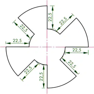
This diagram shows where linear dimensions should be placed on sloping edges. What is the general guidance for orienting linear dimensions on sloping edges?
Always align the dimension text with the horizontal axis only.
Place linear dimensions so they can be read from the bottom or right-hand side and align the dimension line parallel to the sloping edge where appropriate.
Use vertical dimensions exclusively on sloping edges.
Do not dimension sloping edges.

Angular dimensions around a circular part can be positioned using either of the illustrated methods. Which statement is correct about positioning angular dimensions?
Angular dimensions must be placed at the centre only.
Either distribute equal angle values around the circumference or group them where clarity is best, provided the angles are clearly indicated.
Angles should be converted to linear values for positioning.
Angular dimensions cannot be used on circular features.
Items are manufactured with an acceptable margin of dimensional error called tolerance. Which description best defines tolerance in manufacturing?
A decorative variation in drawing style
The acceptable range within which a dimension may vary while allowing parts to function and assemble
A mandatory change to nominal size on all parts
The exact nominal size with no variation permitted
There are two ways to represent tolerances in drawings. How are non-functional dimensions commonly represented?
By attaching individual tolerance values to each dimension
By a general note in the title block, for example: Tolerances unless otherwise stated: linear ±0.25, angular ±0°30′
By omitting tolerances entirely
By converting all sizes to nominal values only
Which statement correctly distinguishes functional and non-functional dimensions in practice?
Functional dimensions directly affect the function and fit of parts; non-functional dimensions do not directly affect function or fit.
Non-functional dimensions control the fit of parts; functional dimensions address appearance only.
Functional dimensions are optional; non-functional dimensions are mandatory.
Both types have no impact on manufacturing.
For linear dimensions, which description matches the common method of indicating tolerance?
Show nominal size with a symmetrical tolerance band.
Show the upper limit of size placed above the lower limit.
Show the nominal size plus the upper and lower limits of the tolerance band.
Show only the percentage variation.
In linear dimensions, what is meant by symmetrical tolerance?
The nominal size is shown together with equal positive and negative tolerance values about the nominal.
Only the lower limit is given above the upper limit.
The nominal size is omitted and two limits are shown.
The tolerance is applied as an angle rather than a length.
For linear dimensions, what is meant by asymmetrical tolerance?
Equal positive and negative values around the nominal size
Nominal size plus distinct upper and lower limits that are not equal
Only upper and lower limits with no nominal size
Tolerance expressed as a percentage only
Angular dimension tolerances are indicated similarly to linear ones. In the common method for angles, how are limits typically presented?
Only a single nominal angle is shown.
Upper and lower limits of the angle are stated (for example, 90°45′ over 90°15′).
A symmetrical band is always required.
Angles must be converted to radians.
Which statement correctly describes symmetrical tolerance for angular dimensions?
Show the nominal angle with equal positive and negative tolerance values (for example, 45° ± 0°15′).
Show only the upper limit above the lower limit.
Omit the nominal angle entirely.
Express tolerance as linear millimetres.
Which statement correctly describes asymmetrical tolerance for angular dimensions?
Provide the nominal angle plus unequal upper and lower limits (for example, +0°35′, −0°55′).
Give equal positive and negative values about the nominal.
Show only the lower limit above the upper limit.
Replace angles with diameters.
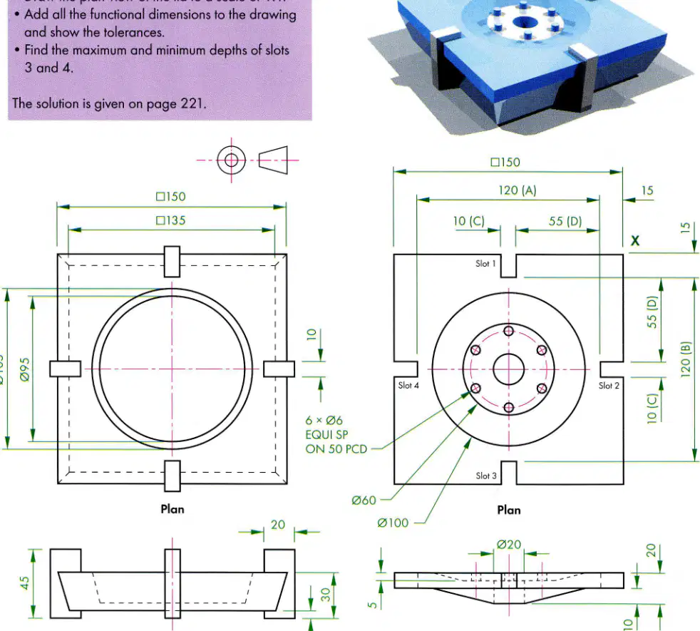
According to the task box, draw the plan view of the lid to the specified scale.
1:1
1:2
2:1
1:5
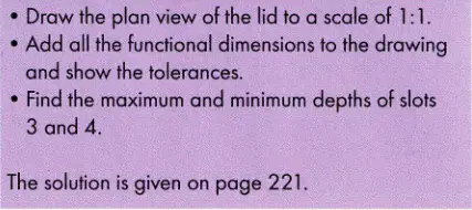
From the task instructions, which dimensions must be added to the drawing and shown with tolerances?
Functional dimensions
Decorative dimensions only
Non-functional dimensions only
Hole center marks only
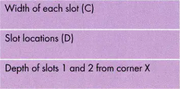
What general tolerance applies to all other (non-functional) dimensions listed in the table?
±0.25
±0.15
+0.15 and 0
−0.2 and −0.3
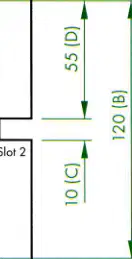
According to the tolerance table, what are the tolerances for the dimension between slots 2 and 4 (A)?
−0.1 and −0.2
−0.1 and +0.2
+0.15 and 0
+0.55 and +0.35
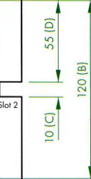
According to the tolerance table, what are the tolerances for the dimension between slots 1 and 3 (B)?
−0.1 and −0.2
+0.15 and 0
−0.2 and −0.3
+0.55 and +0.35
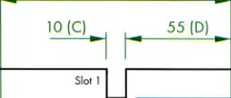
According to the tolerance table, what are the tolerances for slot locations (D)?
−0.2 and −0.3
−0.1 and −0.2
+0.15 and 0
±0.25
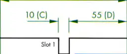
According to the tolerance table, what are the tolerances for the width of each slot (C)?
+0.55 and +0.35
−0.1 and −0.2
−0.2 and −0.3
+0.15 and 0
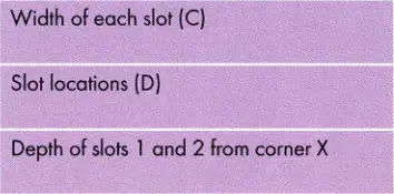
According to the tolerance table, what are the tolerances for the depth of slots 1 and 2 from corner X?
+0.15 and 0
−0.1 and −0.2
+0.55 and +0.35
±0.25
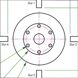
In the lid plan, how many holes of ∅6 are equally spaced on the 50 PCD?
6
4
8
10
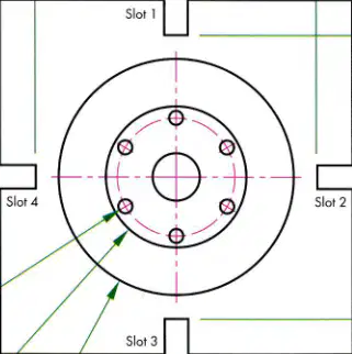
What is the specified pitch circle diameter for the equally spaced ∅6 holes in the lid plan?
50
60
100
20
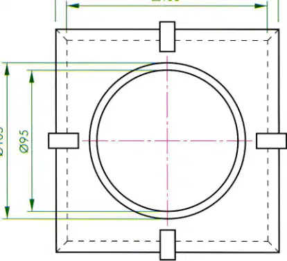
From the lid plan, what is the overall square dimension indicated at the outer edges?
150
135
120
110
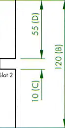
In the lid plan, what is the dimension labeled A for the distance between slots 2 and 4?
120
135
150
110
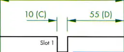
In the lid plan, what is the width of each slot labeled C?
10
15
20
55
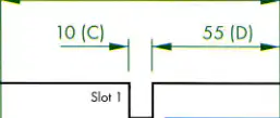
In the lid plan, what is the slot location dimension labeled D?
55
15
10
120
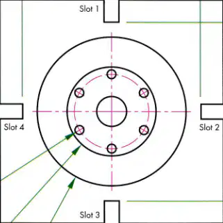
In the lid plan, what is the diameter of the larger concentric circle?
∅100
∅60
∅20
∅50
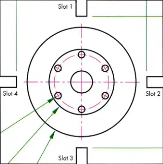
In the lid plan, what is the diameter of the smaller concentric circle inside the larger one?
∅60
∅100
∅20
∅50
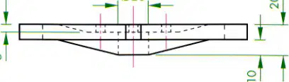
From the lid elevation, what is the diameter of the central through hole?
∅20
∅10
∅30
∅45
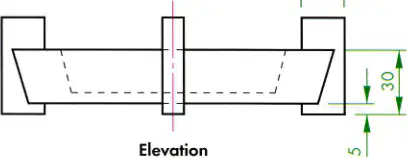
From the base elevation, what is the overall height indicated?
45
30
20
10
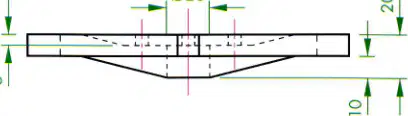
From the lid elevation, what is the overall thickness indicated across the lid?
20
10
30
45
When dimensioning a radius on a drawing, which symbol should be used before the value?
Ø
R
T
M
Which of the following is the best practice when placing dimension lines to avoid confusion in technical drawings?
Arrange dimension lines so they are spaced apart and do not cross other lines whenever possible.
Use only one dimension line for all measurements.
Place all dimension lines inside the object outlines.
Place dimension lines so they cross each other frequently.
What is the main reason for using a general tolerance note in the title block of a drawing?
To specify tolerances for every individual dimension separately
To show the material type
To provide default tolerances for dimensions not otherwise specified
To indicate the drawing is not to scale
Which symbol is used to indicate the diameter of a hole on a technical drawing?
M
R
Ø
D
What is the recommended way to show the tolerance for a linear dimension on a technical drawing?
Display only the nominal size without any tolerance.
Show the upper and lower limits above and below the nominal size.
Express tolerance as a percentage of the nominal size.
Indicate tolerance using a color code.
When dimensioning a chamfer at 30°, which information should be included on the drawing?
Neither length nor angle
Just the angle value
The length and the angle value
Only the length of the chamfer
Which symbol is commonly used to indicate a radius on a technical drawing?
D
R
Ø
T
When dimensioning a hole that is not through the entire part, which additional information should be specified?
Just the depth
Only the material
Only the diameter
The diameter and the depth of the hole
What is the recommended practice for placing dimensions on a drawing to avoid confusion?
Group all dimensions in one corner of the drawing
Place dimensions inside the outlines whenever possible
Arrange dimensions outside the outlines and avoid crossing dimension lines
Use random placement for clarity

