
 Worksheets
PHY6
Total questions: 41
Worksheet time: 3620secs
what does an ohmeter measure
the resistance of a circuit element
the voltage between two points in circuits
the current at some point in the circuit
ohm's law
what does an ammeter measure
the resistance of a circuit element
the voltage between two points in a circuit
the current at some point in the circuit
ohm's law
what does a voltmeter measure
the resistance of a circuit element
the current at some point in the circuit
the voltage between two points in a circuit
ohm's law
if an ammeter is placed in series it is measuring the
actual current
actual voltage
actual capacitance
actual resistance
how do dielectrics affect capacitors connected to a voltage source (battery)
dielectrics lower the electric field leading to a decrease in voltage and a decrease in capacitance
dielectrics reduce the electric field in the capacitor
dielectrics maintain voltage because its hooked up to an internal voltage source
an increase in charge on plates of the capacitor
dielectrics maintain voltage because its hooked up to an external voltage source
how do dielectrics affect isolated capacitors
decrease the voltage and capacitance
increase the voltage and capacitance
lower the electric field
decrease the voltage and increase in capacitance
lowest dielectric constant and the material it belongs to
when there is charge between the plates of a capacitor
vacuum
when there is nothing between the plates of the capacitor
zero
as the electric field between the plates in a capacitor increases...
the capacitance increases
the capacitance decreases
the charge increases
the charge decreases
how do dielectric materials work?
inserted in between the plates of a capacitor in order to increase the capacitance
decrease the strength of electric field between plates in order to increase the capacitance
inserted in between the plates of a capacitor in order to decrease the capacitance
decrease the strength of the electric field between plates in order to decrease the capacitance
reduces energy stored in capacitor
what is a dielectric material
insulator
glass
air
plastic
what physical properties affect capacitance
the distance between the plates and the cross sectional area of the plates
the resistance between the plates and the cross sectional area of the plates
the current between the plates and the cross sectional area of the plates
the cross sectional area of the plates
SI unit for capacitance
F
C/V
J/C
A/V
what is capacitance
the ratio of the amount of charge built up on either plate of the capacitor to the magnitude of the voltage across the capacitor
the ratio of the amount of current built up on either plate of the capacitor to the magnitude of the voltage across the capacitor
the amount of charge built up on either plate of the capacitor
the magnitude of the voltage across the capacitor
capacitors store energy in the form of
charges
magnetic field
electric field
heat
how does a parallel plate capacitor work?
one plate is connected to the positive terminal and connected to the negative terminal separated by a small distance.
a positive and negative terminal on one plate separated by a small distance.
the differences in charges causes an electric field to develop between plates
the differences in charges causes a magnetic field to develop between plates
what is a capacitor?
an electrical element that can store energy within itself
an electrical element that resists the flow of electrons through itself
an electrical element that cannot store energy within itself
an electrical element that allows the flow of electrons through itself
what is a resistor?
an electrical element that can store energy within itself
an electrical element that resists the flow of electrons through itself
an electrical element that cannot store energy within itself
an electrical element at pushes the flow of electrons through itself
in a parallel configuration each element will feel the same...
voltage
current
capacitance
resistance
how to calculate the equivalent resistance for resistors in series?
R1 + R2 + R3 ...
1/R1 + 1/R2 + 1/R3 ...
C1 + C2 + C3 ....
1/C1 + 1/C2 + 1/C3 ...
how to calculate the equivalent resistance for resistors in parallel?
R1 + R2 + R3 ...
1/R1 + 1/R2 + 1/R3 ...
C1 + C2 + C3 ...
1/C1 + 1/C2 + 1/C3 ...
how to calculate the equivalent capacitance for capacitors in series?
R1 + R2 + R3 ...
1/R1 + 1/R2 + 1/R3 ...
C1 + C2 + C3 ...
1/C1 + 1/C2 + 1/C3 ...
how to calculate the equivalent capacitance for capacitors in parallel?
R1 + R2 + R3 ...
1/R1 + 1/R2 + 1/R3 ...
C1 + C2 + C3 ...
1/C1 + 1/C2 + 1/C3 ...
what does it mean for elements to be in parallel?
elements that are placed sequentially on the same path
elements that are placed side by side on different paths
current is split and distributed amongst the elements
voltage is split and distributed amongst the elements
what does it mean for elements to be in series?
elements are placed side by side on different paths
elements are placed sequentially on the same path
current is split and distributed amongst the elements
voltage is split and distributed amongst the elements
in a circuit current flows from
positive terminal to negative terminal
negative terminal to positive terminal
resistor to capacitor
capacitor to resistor
SI unit for resistance
ohm
farad
amp
volt
as temperature increases what happens to a resistors resistance?
increases
decreases
no change
what is the loop rule?
around a closed circuit loop the sum of voltage sources will always be equal to the sum of voltage drops
the sum of all voltages is equal to zero
around an open circuit loop the sum of voltage sources will always be equal to the sum of voltage rops
the sum of all voltages must be greater than zero
what is the junction rule?
the current going into a junction must equal the current going out of a junction
the current going into a junction is less than the current going out of a junction
the current going into a junction is more than the current going out of a junction
the current going out of a junction must equal the current going into a junction
the conservation of energy principle explains
all circuit laws
all voltage laws
all current laws
all of the above
what is electromotive force?
not an actual force
the potential difference between the two terminals of a cell
a potential difference difference that drives the electron through the wire of the circuit
the potential difference between two capacitor plates
what is a current?
the amount of positive charge passing through a conductor per unit of time
flows from high potential to low potential
the amount of negative charge passing through a conductor per unit of time
flows from low potential to high potential
in an electrolytic solution as the concentration of ionic solutes goes up...
conductance decreases
conductance increases
insulation decreases
insulation increases
what is an electrolytic solution?
a solution with dissolved ions
a solution that can conduct electricity through themselves
a solution that can't conduct electricity

A group of students investigated the reactions of several metals with solutions containing metallic ions.
Experiment 1
The students placed strips of a metal, X(s), into solutions containing different metallic ions, Ym+(aq), as shown in Figure 1.
Figure 1Metal strip in solution
After several hours, they observed whether or not Y(s) formed on the surface of the metal strip (see Table 1).
Table 1Results of Metal Strip Experiment

Experiment 2
The students placed a solid strip of each metal into an aqueous solution containing ions of the same metal. Complete circuits were established (Figure 2).

Figure 2Complete circuit
Finally, the students checked a general chemistry text to determine the standard reduction potentials for the following reactions.
Pb2+(aq) + 2e– → Pb(s) E°red = –0.127 V
Reaction 1
Cu2+(aq) + 2e– → Cu(s) E°red = +0.339 V
Reaction 2
A circuit similar to that in Figure 2 is set up. It has a potential of 2.0 V. Assume that the resistance in the circuit is negligible compared to that of the lightbulb. Approximately how much current passes through the lightbulb?
0.5 A
1.0 A
2.0 A
4.0 A
A student can most effectively increase the current passing through the circuit in Figure 2 by doing which of the following?
Using electrical wire with a smaller diameter
Increasing the temperature of the electrical wire
Decreasing the concentrations of Xn+(aq) and Ym+(aq)
Replacing the lightbulb with one that has a resistance of 0.2 Ω

The central nervous system is an example of an electrical system within the human body. Neurons are the basic electrical components of the central nervous system, and exist in three classes: sensory neurons, motor neurons, and interneurons. Each neuron is made of three main components: the nerve cell, the axons, and the dendrites. The longest axons are approximately 1 m in length, and the axon outer membrane is surrounded by an extracellular aqueous solution of protein, sodium, potassium, and chloride ions. A summary of the electrical properties of axons is shown in Table 1 and in Figure 1.
Table 1The Electrical Properties of Axons
Figure 1A segment of a simplified electric circuit model of the axon
Scientists can study the electrical properties of neurons by inserting probes into them to measure voltage changes as a response to stimulus. A typical plot of this action potential is shown in Figure 2.

Figure 2A typical nerve impulse, also known as the action potential
A nerve conduction velocity test (NCV) exploits the electrical properties of neurons to test for nerve damage. In this test, two electrodes are placed on a patient’s body, with an electrical shock placed on one and the nerve response measured on the other. The pulse travels at a constant speed of 100 m/s.
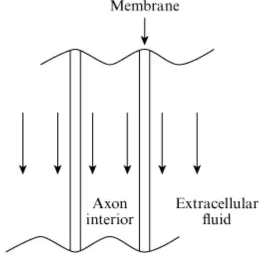
Which image best illustrates the electric field lines between the inside of an axon and the surrounding extracellular solution?



One function of the myelin sheath is to:
insulate the axon from the surroundings.
decrease the radius of the axon.
produce Schwann cells.
increase the capacitance of the axon.
Channel X transmits only the smallest substances dissolved in the extracellular fluid through the axon membrane. Which substance does Channel X transmit?
Proteins
Sodium ions
Potassium ions
Chloride ions
What is the closest distance the electrodes used in an NCV test can be placed on a nerve in order to measure the voltage change as a response to the stimulus?
0.01 m
0.10 m
1.00 m
10.00 m
What information about an axon is required to calculate the current associated with an NCV pulse?
Conductivity, resistivity, and length
Potential, conductivity, and radius
Potential, resistivity, and radius
Potential, resistance per unit length, and length

Researchers performed an experiment to investigate the thermal properties of human skin with regard to heat transfer. For this purpose an iron wire with known electric and thermal properties was mounted in a specially designed holder and placed 5 cm away from the forearm skin of a volunteer. The design enabled heat from the wire to be transferred to the skin. At room temperature the wire had a length L of 4 m, a diameter D of 4 × 10⁻⁴ m, and a mass M of 4 × 10⁻³ kg. The wire was connected in series with an ammeter, a power supply, and a switch.
The researchers selected a voltage (V) and closed the switch so current (I) flowed through the circuit, raising the wire’s temperature (T). The values in Table 1 were measured in five trials with different wire temperatures. (Note: The initial value of R, the circuit’s resistance, was measured at a temperature of 293 K with an ohmmeter. The other values of R were calculated from the values of V and L.)
Table 1Data for Thermal and Electrical Properties of Iron Wire
The change in wire length (ΔL) is related to the change in temperature (ΔT) by the relationship ΔL = αLΔT, where α, the coefficient of thermal expansion, is a constant. A similar relationship, ΔD = αDΔT, describes how the diameter of a wire changes when it is heated. The constant has the same value in both equations.
The energy radiated from a heated wire each second is AσT4, where A is the surface area of the wire, and σ = 5.67 × 10⁻⁸ J/m2·s·K4 is the Stefan·Boltzmann constant.
Which of the following graphs best illustrates the relationship between T and R?


During Trial 5, the wire was heated from 293 K to 673 K while V was held constant at 28 V. How did the current through the circuit change during this time?
It remained constant at 2 A.
It remained constant at 4.6 A.
It increased from 2 A to 4.6 A
It decreased from 4.6 A to 2 A.

The most common cause of sudden cardiac arrest is ventricular fibrillation, an event in which the heart loses its electrical coordination. The only known cure for ventricular fibrillation is early defibrillation: a carefully timed electrical shock to the myocardium.
The principal component of a defibrillator is a capacitor. It is charged by placing the switch in Position C in Figure 1.
Figure 1 Schematic of a defibrillator
The capacitor consists of a pair of metal plates separated by a dielectric. During defibrillation the switch is placed in Position D, discharging the capacitor through paddles pressed against the chest of the patient. Firm force (~100 N) and a conductive gel pad are used to improve the electrical contact between each paddle and the patient’s chest.
For successful defibrillation the current delivered must be maintained for several milliseconds. Because the current in an RC circuit decays rapidly and exponentially, an inductor is added to the circuit to extend the duration of current flow.
Successful defibrillation also depends on the delivery of electrical charge to the myocardium. Only a fraction of the total current delivered by the defibrillator flows through the heart. The rest is dissipated by the resistance of the skin and the rest of the body. The resistances of the skin and the thoracic wall act as resistances in series, and the resistance of the other intrathoracic structures acts as a resistance in parallel with that of the myocardium.
Based on the passage, which of the following is closest to the pressure exerted on the chest by a 10 × 5 cm rectangular paddle during defibrillation?
(Note: 1 Pa = 1 N/m2.)
5 kPa
10 kPa
15 kPa
20 kPa
If the defibrillator described in the passage were fully charged and the entire charge were discharged through a patient in 10 ms, which of the following is closest to the average electrical current that would flow through the paddles?
7.5 A
15 A
22.5 A
30 A
If both the capacitor and the power supply in Figure 1 are adjustable, which of the following changes would result in an increase in the charge on the capacitor?
Decreasing the area of the parallel plates
Decreasing the separation between the parallel plates
Removing the dielectric from the capacitor
Decreasing the voltage of the power supply
If the 25 μF capacitor in the defibrillator in Figure 1 is replaced with a 30 μF capacitor, what new power supply setting would produce the same amount of charge?
3600 V
3500 V
3000 V
2500 V

A vacuum photodiode detector utilizes the photoelectric effect to detect light. The photoelectric effect causes electrons to be ejected from a metal plate when photons of light are absorbed by the metal. The energy of a photon is given by the equation E = hf, where h = 6.6 x 10⁻³⁴J·s (Planck’s constant), and f is the frequency of the photon. To free an electron, the energy of a photon must be greater than a quantity called the work function of the metal. The ejected electron will have a kinetic energy equal to the photon’s energy minus the work function.
A vacuum photodiode is constructed by sealing two electrodes, a cathode and an anode, in a vacuum tube. The electrodes are separated by a distance, L = 0.01 m, and connected to a battery and a resistor, R = 100 Ω, as shown in Figure 1. The cathode is made of a photoelectric metal and is connected to the negative terminal of the battery. The potential difference between the cathode and anode is approximately equal to the battery voltage, V = 50 V. The electric field at all points between the electrodes is equal to the electrode voltage difference divided by L. The potential energy of an electron immediately after it is released from the cathode is equal to qV, where q = -1.6 x 10⁻¹⁹C is the charge of an electron. The work function for the vacuum photodiode is 2 x 10-19J.
Which of the following changes to the circuit will decrease the electric field between the electrodes by the greatest amount?
Increasing L by a factor of 2
Decreasing L by a factor of 2
Increasing R by a factor of 2
Decreasing R by a factor of 2
An electron is ejected from the cathode by a photon with an energy slightly greater than the work function of the cathode. How will the final kinetic energy of the electron upon reaching the anode compare to its initial potential energy immediately after it has been ejected?
It will be 2 times as large.
It will be approximately equal.
It will be 1/4 as large.
It will be 0.
When the number of photons incident on the cathode with energies above the value of the work function increases, which of the following quantities also increases?
Number of electrons ejected
Potential energy of each ejected electron
Magnitude of the electric field between the electrodes
Speed of electrons at the anode
Which of the following best describes the movement of an electron after it is ejected from the cathode?
It is stationary until collisions propel it toward the anode.
It moves with constant speed toward the anode.
It accelerates toward the anode.
It exits through a side of the vacuum photodiode.
Which of the following occurs when electrons are ejected from the cathode?
The voltage across the electrodes reverses polarity.
The voltage difference between the electrodes increases.
Current flows through the circuit.
The total resistance of the circuit increases.
Increasing the frequency of each photon that is directed at the cathode will:
decrease the number of photons ejected.
increase the number of photons ejected.
decrease the speed of the ejected electrons.
increase the speed of the ejected electrons.

Students constructed the electrical circuit shown below to study capacitors. A battery with a voltage of 10 V is connected through a switch to a capacitor and a 500-Ω resistor. The capacitor is constructed from two flat metal plates, each with a surface area of 5.0 × 10⁻⁵ m2. The plates are separated by 1.0 × 10⁻³ m, and the space between the plates is a vacuum. The connecting wires have no resistance. After the switch is closed and the capacitor is fully charged, a particle with a charge of 8.0 × 10⁻¹⁹ C and a speed of 1.0 m/s is injected midway between the capacitor plates.
If the speed of the charged particle described in the passage is increased by a factor of 2, the electrical force on the particle will:
decrease by a factor of 2.
remain the same.
increase by a factor of 2.
increase by a factor of 4.
Making which of the following changes to a circuit element will increase the capacitance of the capacitor described in the passage?
Replacing the 500-Ω resistor with a 250-Ω resistor
Replacing the 10-V battery with a 20-V battery
Increasing the separation of the capacitor plates
Increasing the area of the capacitor plates
A charged particle with a mass of m and a charge of q is injected midway between the plates of a capacitor that has a uniform electric field of E. What is the acceleration of this particle due to the electric field?
Eq/m
Em/q
mq/E
Emq
Another capacitor, identical to the original, is added in series to the circuit described in the passage. Compared to the original circuit, the equivalent capacitance of the new circuit is:
1/2 as great
the same.
2 times as great.
4 times as great.
Which of the following best describes the motion of a negatively charged particle after it has been injected between the plates of a charged, parallel-plate capacitor? (Note: Assume that the area between the plates is a vacuum.)
It moves with constant speed toward the positive plate.
It moves with constant speed toward the negative plate
It accelerates toward the positive plate.
It accelerates toward the negative plate.

A capacitor is a device that stores charge. The voltage V across a capacitor and the charge q on the capacitor are related by q = CV, where C is the capacitance measured in farads, F (1.0 F = 1.0 coulomb per volt).
A student sets out to measure the capacitance using the circuit of Figure 1.
Figure 1Circuit for measuring capacitance
In this circuit, the capacitor will be fully charged soon after switch S is closed to the left, as current passes through the small fixed resistor r in series with the capacitor C. Then, when S is switched to the right, the capacitor discharges through the variable resistor R. R is adjusted so that the discharge current, as measured by the ammeter, is constant during the discharge time.

Figure 2The discharge current versus time
Figure 2 shows the current-versus-time plot during the discharge. The voltage of the battery used in the measurement was 12.0 V. The total charge q transferred to the capacitor can be estimated from the constant current value during the discharge time.
When switch S is closed to the left, charge begins to accumulate on the capacitor. Charge cannot accumulate indefinitely because:
the variable resistor inhibits the current flow.
the battery continually loses charge.
successive charges brought to the plates are repelled by charges accumulated earlier.
the fixed resistor loses energy to heat.
To keep the current constant during the discharge cycle:
the resistance R must be continually increased.
the resistance R must be continually decreased.
the resistance r must be continually increased.
the resistance r must equal R.
Which circuit elements store energy?
I. Capacitors
II. Resistors
III. Batteries
I only
I and II only
I and III only
II and III only
The resistance of the variable resistor, R, at the beginning of the discharge process is:
2000 Ω.
3000 Ω.
4000 Ω.
6000 Ω.

