
Font size
 Worksheets
Beam Deflection and Slope Calculation (Question 2.1)
Total questions: 23
Worksheet time: 1hrs 2mins
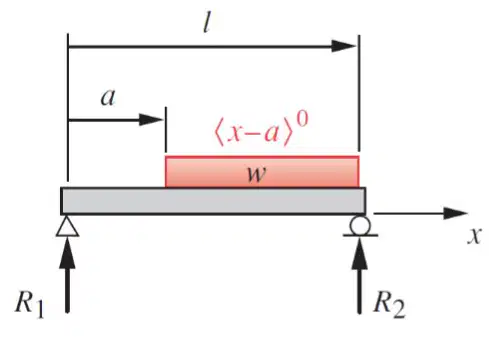
In the given figure, l=1 m , a=0.4 m , w=200 N/m , I=3×10⁻⁸ m4 , and the material is steel. Using beam tables, please find the deflection midspan of the beam.
Derive an equation for the beam’s slope, starting with the loading function. The equation should be in terms of the unknown variable x . Use this equation to solve for the slope at the leftmost support.
Using the loading function approach for the same beam, write expressions for the distributed load q(x) , shear V(x) , moment M(x) , rotation Θ(x) , and deflection y(x) including the integration constants. Then determine the constants using boundary conditions and compute the rotation at the right support Θ(l) .
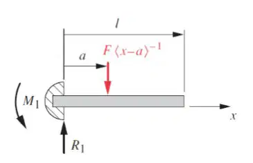
In the given figure, l = 1 m, a = 0.35 m, F = 800 N, I = 2 \times 10^{-8} m^{4}, and the material is aluminum. Using beam tables, please find the deflection at the end of the beam.
Derive an equation for the beam’s deflection, starting with the loading function. The equation should be in terms of the unknown variable x. Use this equation to solve for the deflection x distance from the leftmost support.
The value of x that should be used for the deflection calculation is x =
(a)
Apply the boundary conditions θ(0) = 0 and y(0) = 0 to your derived expressions for slope and deflection. State the resulting integration constants.
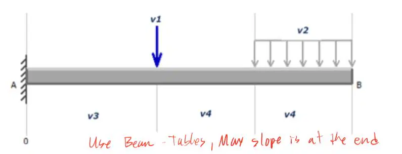
For the beam shown, calculate the maximum slope. You may use either beam tables or you can derive the expression from loading function.
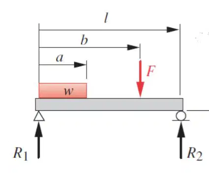
Using beam tables, please find the deflection 0.4 m from the leftmost support. In the given figure, l = 0.9m , a = 0.3m , b = 0.75m , w = 150N/m , F = 600N , I = 5.1×10⁻⁸m4 , and the material is steel. Support reactions are at R1 (left) and R2 (right). A uniformly distributed load of intensity w acts over length a starting from the left support, and a concentrated load F is applied at a distance b from the left support on a simply supported beam of span l.
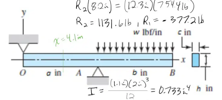
For the beam illustrated in the figure, what is the deflection midway between the two supports? Parameters are segment OA = 8.20 in, segment AB = 8.20 in, c = 1.100 in, h = 2.000 in, h̄ = 2.000 in, and w = 92.0 lbf/in. Use the given distributed load diagram and the expression y = 24EIw[(2a2b−4ab2+b3−b1(b−a)4)x+(4a−b2a2)x3−x4+(x−a)4+b2a2(x−b)3] .
Repeat the calculation for the same beam if a = 8.2 in and b = 8.2 in, using the expression y = 24EIw[(2a2b−4ab2+b3−b1(b−a)4)x+(4a−b2a2)x3−x4+(x−a)4+b2a2(x−b)3] . Evaluate at x = 4.2 in.
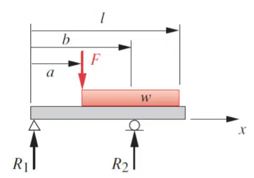
In the given figure, l = 0.6 m, a = 0.18 m, b = 0.45 m, w = 250 N/m, F = 150 N, I = 3.2 \times 10^{-9} m^{4}, and the material is steel. For the beam illustrated in the figure, find the deflection 0.15 m from the leftmost support.
Using the superposition sketches and expressions provided, evaluate the contribution to deflection at x = 0.15 m from the left support due to the uniform distributed load acting over the entire span length a2 = 0.6 m and then adjust for the truncated region with b = 0.45 m as shown.
Using the superposition sketches and expressions provided, evaluate the contribution to deflection at x = 0.15 m from the left support due to the uniform distributed load acting over the left region with a2 = 0.18 m and b = 0.45 m as shown.
Combine the superposed deflections to obtain the net deflection at x = 0.15 m from the left support for the beam: y = y3−y1−y2 . Use the given values l = 0.6 m, a = 0.18 m, b = 0.45 m, w = 250 N/m, F = 150 N, I = 3.2 \times 10^{-9} m^4, and steel for material.
For the point-load case shown, use the provided expression y1=(F/(6EI))[((b−a)/b)x3+(a/b)(x−b)3−(x−a)3+b(a−b)x+…] to compute the deflection contribution at x = 0.15 m with a = 0.18 m, b = 0.45 m, and F = 150 N. Treat the missing term indicated as not provided.
The figure shows a cantilever beam made of steel angles size 100 mm × 100 mm × 12 mm mounted back to back. Take F = 3.0 kN/m and a = 2.4 m. Find the deflection at the end of the beam. Find the deflection 0.5 m from the leftmost support.
y1 = \frac{1{,}000\ \text{N/m}}{24\,[207\ \text{cm}^4]\,2\,(206.86\ \text{GPa})}\Big((\frac{4}{3}L)(0.5\ \text{m})^3 - 6(3L^2)(0.5\ \text{m})^2 - (0.5\ \text{m})^4\Big) y2 = \frac{3{,}000\ \text{N}}{6\,[207\ \text{cm}^4]\,2\,(206.86\ \text{GPa})}\Big((0.5\ \text{m})^3 - 3(2.4\ \text{m})(0.5\ \text{m})^2 - 0\Big) Using the provided expressions, determine the deflection 0.5 m from the leftmost support by evaluating y = y1 + y2.
The figure shows a cantilever beam made of two structural-steel channels. Each steel channel is of size 3 in., 5.0 lbf/ft and mounted back to back. Take F = 200 lb, applied load of w = 4 lbf/in, and L = 60 in. Find the deflection at the end of the beam. Find the deflection 40 in from the leftmost support.
The beam is pinned at the leftmost support and suspended by a metal, circular rod that is made from 1020 cold rolled steel. Use superposition to determine the vertical deflection at point A. F = 200 N and the beam cross-section is rectangular (12 mm thick). NOTE: The overall deflection should be found by summing the deflection at A assuming the beam operates as a rigid body with the deflection at A assuming location D is pinned (providing the condition similar to an overhung beam). All dimensions in mm. Locations: O at left pin, A is 150 mm from O, D is 450 mm from O, B is 650 mm from O. A vertical load F acts at B; a vertical rod of 6 mm diameter connects at C above the beam near D; the rod length is 220 mm. Determine the vertical deflection at A.
Given the beam-and-rod system described, identify which principle allows the total deflection at point A to be obtained by summing deflections from separate simpler cases.
Compatibility of displacements
Superposition of linear systems
Work-energy theorem
Conservation of momentum
Use the provided overhung-beam deflection expression y1=6EIF[bb−ax3+ba(x−b)3−(x−a)3+b(a−b)x] with a=0.15m , b=0.65m , and x=0.15m to express the elastic-beam contribution to deflection at A symbolically in terms of F , E , and I .
In the context of this problem, what geometric property of the beam section is needed to compute bending deflection using the formula y1=6EIF[⋯] ?
Cross-sectional area
Polar moment of inertia
Second moment of area about the neutral axis
Radius of gyration

